TECHNICAL DATA
I42TD – I60TD
Rev. 00
January 2005
10/36
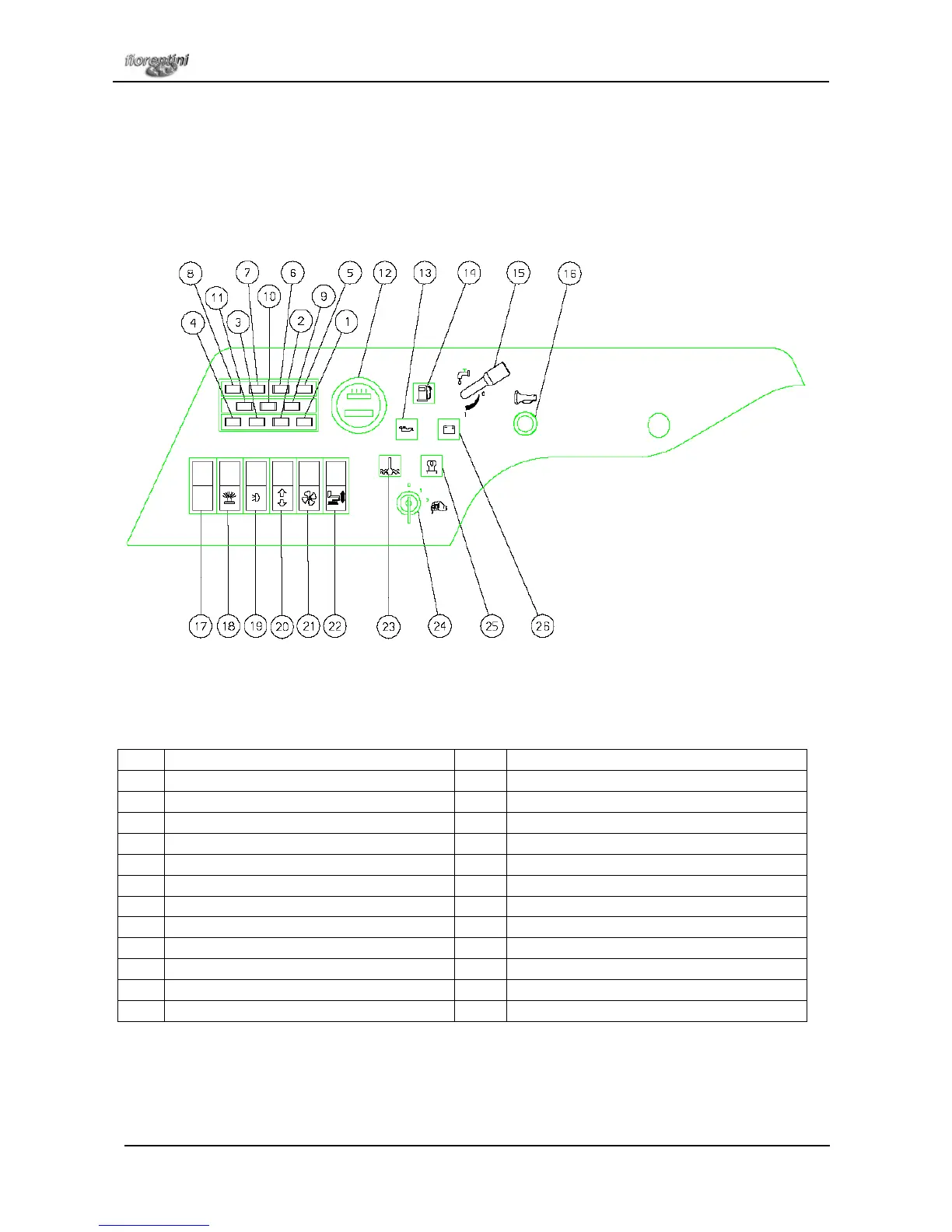
4.3.1. DASHBOARD
The dashboard is made of a series of switches that activate or disactivate all the machine functions. The
function of each switch is shown by a picture. Picture 4.6. shows the dashboard of the machine and the
switches function is explained in the scheme below.
1 Flashing light fuse 14 Petrol level pilot light
2 Lights fuse 15 Solution regulation lever
3 Oil cooling fan fuse 16 Horn button
4 Solenoid valves main fuse 17 Sweeping assy (accessori)
5 Feed fuse 18 Flashing light switch
6 Direction indicator and stop fuse 19 Lights switch
7 Empty 20 Squeegee up/down
8 Empty 21 Suction motors switch
9 Empty 22 Brushes on/off-up/down
10 Empty 23 Diesel engine temperature switch
11 Empty 24 Key switch
12 Timer manometer 25 Glow plugs pilot light
13 Oil pressure pilot light 26 Battery charger pilot light