7
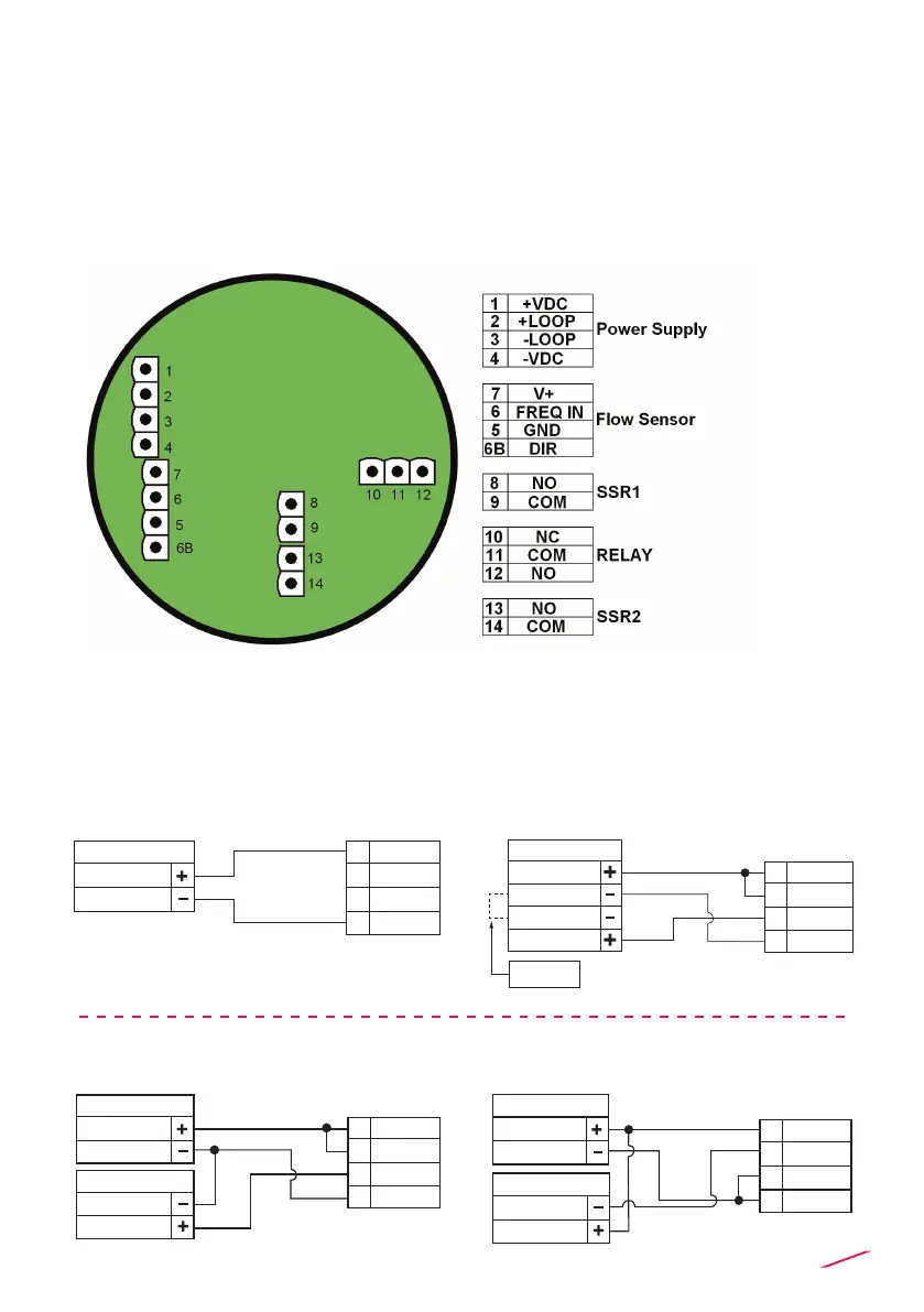
REAR TERMINAL VIEW
POWER/LOOP WIRING DIAGRAM
Compact or Wall Installation
Pull the electrical cables through liquid tight connectors.
Use electrical cables with the proper external diameter for the liquid tight
connector.
PG11/PG9: external diameter between 2-7 mm (0.079-0.276”)
Refer to dedicated sensor manual for its wiring.
Stand-alone application,
no current loop used
Connection to a PLC/Instrument with ONE separate power supply
or
Connection to a PLC with built-in
power supply (3 wire connection)
Power Supply
12 - 24 VDC
12 - 24 VDC
+ VDC
- VDC
+ LOOP
- LOOP
1
2
3
4
Power Supply
Power Supply
Internal PLC
connection
4 - 20mA Loop Input
4 - 20mA Loop Input
PLC Terminals
+ VDC
- VDC
A
+ LOOP
- LOOP
1
2
3
4
Power Supply
12 - 24 VDC
12 - 24 VDC
PLC / Instrument
4 - 20mA Loop Input
4 - 20mA Loop Input
Power Supply
12 - 24 VDC
12 - 24 VDC
PLC / Instrument
4 - 20mA Loop Input
4 - 20mA Loop Input
+ VDC
- VDC
A
+ LOOP
- LOOP
1
2
3
4
+ VDC
- VDC
+ LOOP
- LOOP
1
2
3
4
Power Supply
12 - 24 VDC
12 - 24 VDC
PLC / Instrument
4 - 20mA Loop Input
4 - 20mA Loop Input
Power Supply
12 - 24 VDC
12 - 24 VDC
PLC / Instrument
4 - 20mA Loop Input
4 - 20mA Loop Input
+ VDC
- VDC
A
A
+ LOOP
- LOOP
1
2
3
4
+ VDC
- VDC
+ LOOP
- LOOP
1
2
3
4
 Loading...