6
WIRING
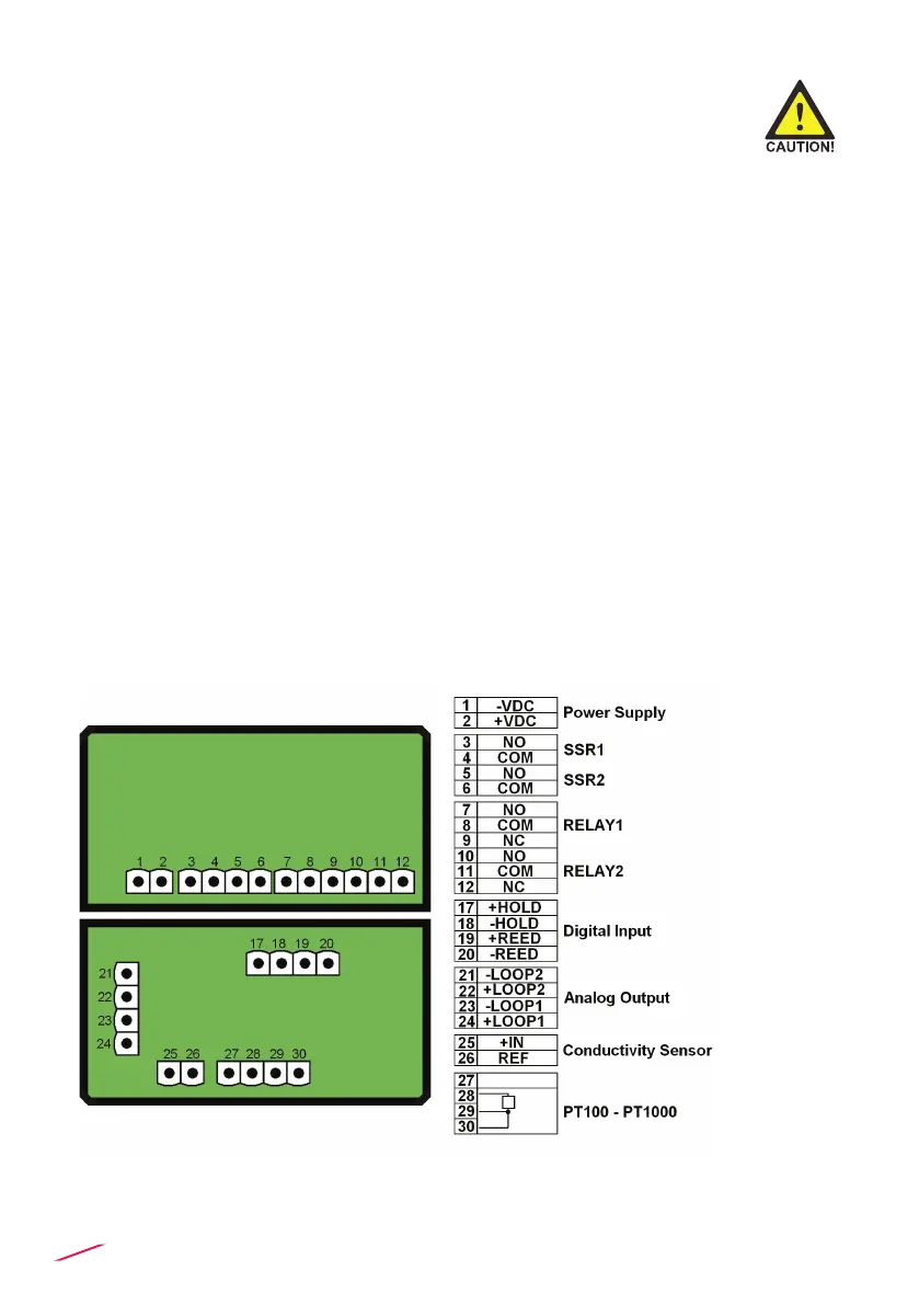
REAR TERMINAL VIEW
General recommendation
Always ensure the power supply is switched off before working on the device.
Make wiring connections according to wiring diagrams.
• Terminals accept 26 to 12 AWG (0.08 to 2.5 mm2)
• Strip around 10 mm (0.4”) of insulation from the wire tips and tin bare ends to
avoid fraying.
• Ferrules are suggested when connecting more than one wire to a single
terminal.
• Remove the upper part of the terminals for an easy cabling.
• Insert wire tip or ferrule completely into the terminal and x with the screw
until nger tight.
• Do not route the sensor, DC power, or 4-20mA cables in conduit containing
AC power wiring. Electrical noise may interfere with sensor signal.
• Routing the sensor cable in grounded metal conduit can help prevent
electrical noise and mechanical damage.
Wall Installation
Pull the electrical cables through liquid tight connectors.
Use electrical cables with the proper external diameter for the liquid tight
connector.
PG11/PG9: external diameter between 2-7 mm (0.079-0.276”)
 Loading...