7
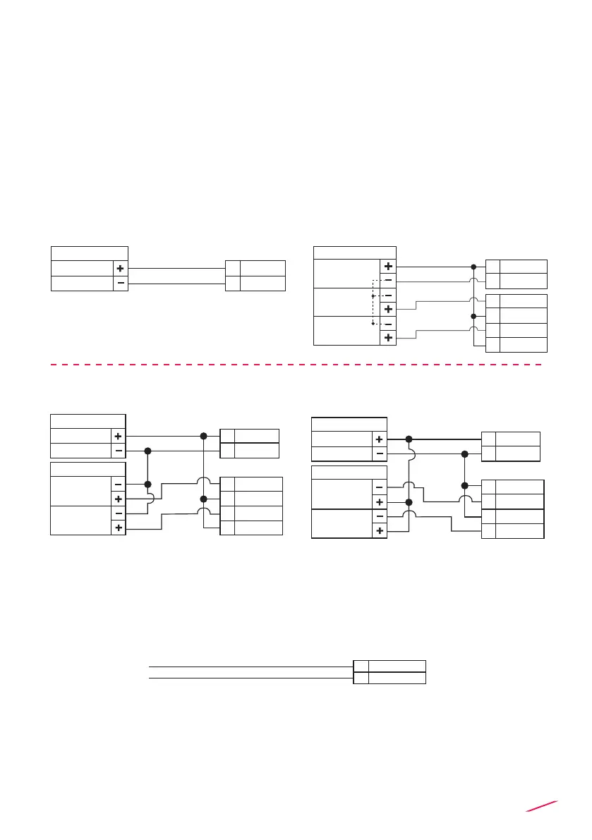
POWER/LOOP WIRING DIAGRAM
Refer to dedicated sensor manual for its wiring. In general conductivity
sensor wires can be connected independently without caring about +IN/REF
connectors.
In case a temperature sensor (Pt100-Pt1000) is not available, place a brigde
connection between 28 - 29 and between 29 - 30.
Stand-alone application,
no current loop used
Connection to a PLC/Instrument with a separate power supply
or
Connection to a PLC with built-in
power supply
Power Supply
12 - 24 VDC
12 - 24 VDC
+ VDC
- VDC
2
1
Power Supply
12 - 24 VDC
4 - 20 mA
Input 2
PLC Terminals
4 - 20 mA
Input 1
+ VDC
- VDC
2
1
- LOOP 2
+ LOOP 1
+ LOOP 2
- LOOP 1
21
22
23
24
Power Supply
12 - 24 VDC
12 - 24 VDC
PLC
4 - 20 mA
Input 2
4 - 20 mA
Input 1
+ VDC
- VDC
2
1
- LOOP 2
+ LOOP 1
+ LOOP 2
- LOOP 1
21
22
23
24
Power Supply
12 - 24 VDC
12 - 24 VDC
PLC
4 - 20 mA
Input 2
4 - 20 mA
Input 1
+ VDC
- VDC
2
1
- LOOP 2
+ LOOP 1
+ LOOP 2
- LOOP 1
21
22
23
24
Power Supply
12 - 24 VDC
12 - 24 VDC
PLC
4 - 20 mA
Input 2
4 - 20 mA
Input 1
+ VDC
- VDC
2
1
- LOOP 2
+ LOOP 1
+ LOOP 2
- LOOP 1
21
22
23
24
Power Supply
12 - 24 VDC
12 - 24 VDC
PLC
4 - 20 mA
Input 2
4 - 20 mA
Input 1
+ VDC
- VDC
2
1
- LOOP 2
+ LOOP 1
+ LOOP 2
- LOOP 1
21
22
23
24
PROBE WIRING DIAGRAM
Conductivity probe connection
In general conductivity sensor wires can be connected independently without
caring about +IN/REF connectors.
25
26
+IN
REF
Conductivity Sensor
 Loading...