9
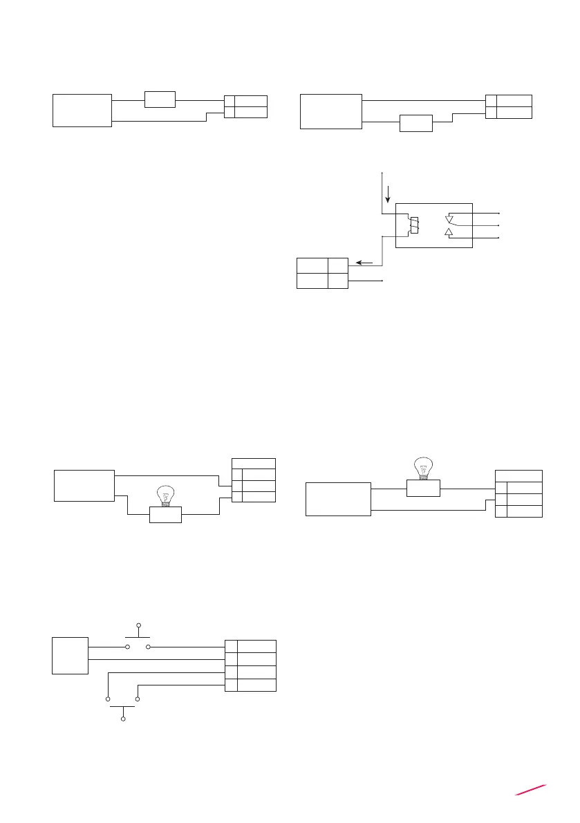
SOLID-STATE RELAY WIRING DIAGRAM
(FOR SSR1 AND SSR2)
RELAY WIRING DIAGRAM
(FOR RELAY 1 & RELAY 2)
HOLD AND REED CONNECTION
The alarm is OFF during normal
operation and goes ON according to
Relay settings
The alarm is ON during normal
operation and goes OFF according to
Relay settings
The alarm is off during normal
operation and goes ON according to
Relay setting.
If Imax > 50 mA use external Relay
Connection to an User
NO
10
11
12
RELAY 2
NC
COM
Alarm
AC or DC
Power
NO
10
11
12
RELAY 2
NC
COM
Alarm
AC or DC
Power
N.O. 3
4 COM
AC or DC
Power
User
Imax = 50mA
N.O. 3
4 COM
AC or DC
Power
User
lmax = 50mA
N.O. 3
4 COM
AC or DC
Power
User
Imax = 50mA
N.O. 3
4 COM
AC or DC
Power
User
Imax = 50mA
lmax = 50mA
N.O.
N.O.
N.C.
COM
4
3
COM
External Relay
V= 12-24 VAC/VDC
Imax = 50 mA
Imax
Imax
+V
-V
lmax = 50mA
- HOLD
+ HOLD
18
17
19
20
- REED
+ REED
12-24
VDC
 Loading...