Do you have a question about the Fire-Lite Alarms LCD-40 and is the answer not in the manual?
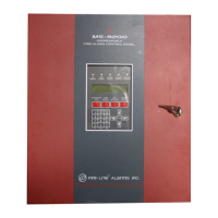
Overview of the LCD-40 annunciator and its compatibility with the MS-9200 panel.
Lists the key capabilities and characteristics of the LCD-40 annunciator.
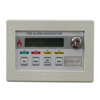
Visual breakdown and identification of the LCD-40's physical components.
Configuration options via SW1 DIP switch for local functions and operation.
Illustrates the standard wiring and setup for the LCD-40 system.
Describes how the LCD-40 displays system messages and status.
Explains how the key-switch enables or disables function keys.
Details the operation and effects of the Acknowledge button.
Describes the Silence button's functions and impact on alarms.
Explains how to activate the drill function and its effects.
Details the system reset procedure and its consequences.
Describes the purpose and behavior of the system status LEDs.
Steps for preparing the LCD-40 unit for installation.
Instructions for physically mounting the LCD-40 into a backbox.
Guide for connecting the power supply to the LCD-40.
Details wiring for the EIA-485 serial communication interface.
Explains connections involving the DIM-485 module.
Illustrates the overall wiring between the FACP and LCD-40 units.
How to terminate EIA-485 shields when not using conduit.
How to terminate EIA-485 shields when using conduit.
The LCD-40 Remote Fire Annunciator is a compact and attractive device designed for use with the Fire-Lite MS-9200 Addressable Fire Alarm Control Panel. It serves as a remote display and control interface, mimicking the LCD display found on the MS-9200 main circuit board. This annunciator is capable of displaying English-language text, providing detailed system point status, including device type, independent point alarm, trouble, or supervisory conditions, as well as zone and custom alpha labels programmed into the control panel. It also shows the current time and date, along with the device address.
The primary function of the LCD-40 is to provide remote annunciation and control capabilities for the MS-9200 FACP. It communicates with the control panel via a two-wire serial interface using the EIA-485 communication standard. Up to 32 LCD-40 units can be connected to a single EIA-485 circuit.
The annunciator features a 40-character LCD display (20 characters x 2 lines) that is backlit under both normal and alarm conditions, ensuring visibility. It includes dedicated System Status LEDs for Power (green), Alarm (red), Trouble (yellow), and Supervisory (yellow), providing a quick visual overview of the system's state.
A key feature of the LCD-40 is its ability to perform remote system functions through its control buttons and an enable key-switch. These functions include:
The LCD-40 includes a local piezo sounder that activates upon receiving any new alarm or trouble from the panel (if enabled). This sounder is silenced by the Acknowledge switch. DIP switches allow configuration of local functions, such as enabling/disabling the piezo sounder, control switches, and key-switch, as well as setting the transmit/receive mode.
The LCD-40 is designed for ease of use and installation. It requires no programming, as it duplicates messages directly from the control panel display. This "no programming necessary" feature simplifies setup and ensures consistency with the main FACP.
The annunciator supports surface or semi-flush mounting in a three-gang electrical box with a minimum depth of 2.125 inches. It can be located up to 3,000 feet from the main panel, offering flexibility in placement within a facility.
The key-switch provides an important security feature, allowing authorized personnel to enable or disable the membrane switches for remote functions. When enabled, the key-switch allows the Acknowledge, Silence, Drill, and Reset functions to be used. When disabled, these functions are locked out, preventing unauthorized operation. The key-switch should normally be in the disabled position with the key removed and access restricted to authorized personnel.
In the event of a power failure, the LCD-40's backlight turns off to conserve battery power but will reactivate if an alarm condition occurs. This ensures critical information remains visible during emergencies.
The LCD-40 incorporates plug-in terminal blocks for easy installation and service, simplifying wiring and maintenance tasks.
The system provides clear indications of its operational status. Upon power-up, it may display "SYSTEM POWER UP WAITING FOR THE 9200" until it receives a valid message from the MS-9200. If communications with the panel are lost for more than 30 seconds, the local sounder will activate (if programmed), and the display will show "COMMUNICATIONS FAIL," alerting users to a potential issue. When the host MS-9200 enters certain programming modes, the LCD-40 will display "PROGRAMMING THE MS-9200 PANEL."
The annunciator's design emphasizes reliability, with adherence to proper grounding procedures to reduce susceptibility to lightning-induced transients. All enclosures, including the LCD-40 electrical box, must be connected to earth ground for static protection.
The EIA-485 communication circuit requires specific wiring practices, including the use of twisted-shielded pair cable and proper shield termination, to ensure reliable data transmission and protection against radiated noise emission (RFI, EMI). Resistors are required across the In and Out terminals for impedance matching on the EIA-485 loop.
The LCD-40 is designed to operate within specific environmental conditions (0-49° C/32-120° F and 85% RH non-condensing at 30° C/86° F). Installing the system in an environment with a nominal room temperature of 15-27° C/60-80° F is recommended to prolong the useful life of standby batteries and electronic components.
Regular testing and maintenance of the entire fire alarm system, including the LCD-40, are crucial for its proper operation. This includes verifying adequate wire sizes for all device loops and ensuring that the piezo sounder is not disabled without approval from the Local Authority Having Jurisdiction (LAHJ).
| Model | LCD-40 |
|---|---|
| Display Type | LCD |
| Power | 24 VDC |
| Backlight | Yes |
| Operating Temperature | 32°F to 120°F (0°C to 49°C) |
| Humidity Range | 10% to 93% non-condensing |
| Mounting | Surface |
| Compatibility | Compatible with Fire-Lite devices |