Page 2 of 2 — DF-52211 • 02/16/05
•
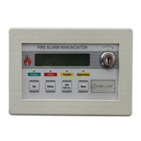
Control buttons:
— ACK (Acknowledge)
— Alarm Silence
— Reset
— Walk Test
— Zone Enable/Disable (one per zone)
•
LED indicators:
— Fire Alarm (one per zone)
— Supervisory (one per zone)
— Trouble (one per zone)
— Maintenance (one per zone)
— AC Power
— NAC Disable
— Zone Disable
— NAC Fault
— System Trouble
— Power Trouble
— Walk Test
— Alarm Silence
— Earth Fault (on circuit board)
— Battery Fault (on circuit board)
— Charger Fault (on circuit board)
• Piezo sounder for alarm, trouble, supervisory and mainte-
nance.
OPERATIONOPERATION
OPERATIONOPERATION
OPERATION
Activation of a compatible smoke detector or any normally-
open fire alarm initiating device activates audible and visual
signaling devices, illuminates an indicating LED, sounds
the piezo sounder at the FACP, activates the FACP alarm
relay and operates an optional module used to notify a
remote station or initiate an auxiliary control function.
SPECIFICATIONSSPECIFICATIONS
SPECIFICATIONSSPECIFICATIONS
SPECIFICATIONS
AC Power — TB8
•
MS-2:
120 VAC, 50/60 Hz, 2.3 A
•
MS-2E:
240 VAC, 50 Hz, 1.15 A.
• Wire size: minimum 14 AWG (2.0 mm²) with 600 V insu-
lation.
Battery (sealed lead-acid only) — J8
• Maximum charging circuit: normal flat charge 27.6 VDC
@ 0.8 A.
• Maximum battery charger capacity: 18.0 AH battery (two
7.0 AH batteries can be housed in the FACP cabinet.
Larger batteries require a separate battery box such as
the Fire•Lite BB-17F).
Initiating Device Circuits — TB3
• Alarm zones 1 & 2.
• Power-limited circuitry.
• Operation: all zones Style B (Class B).
• Normal operating voltage: nominal 22 VDC.
• Alarm current: 15 mA minimum.
• Short-circuit current: 40 mA maximum.
• Maximum loop resistance: 100 ohms.
• End-of-line resistor: 4.7K ohm, 1/2 watt (P/N 71252).
• Standby current: 4 mA.
• Compatible devices: Refer to
Fire•Lite Device Compatibil-
ity Document 15384
for listed compatible devices.
Notification Appliance Circuits — TB2
• One NAC on MS-2.
• Power-limited circuitry.
• Normal operating voltage: nominal 24 VDC.
• Maximum signaling current: 2.5 A total with standard trans-
form.
• End-of-line resistor: 4.7K ohm, 1/2 watt (P/N 71252).
• Compatible devices: refer to
Fire•Lite Device Compatibil-
ity Document 15384
for listed compatible devices.
Form-C Relays
• Trouble Relay TB5 (fail-safe).
• Alarm Relay TB 6.
• Relay contact ratings: 2.0 A @ 30 VAC (resistive).
Auxiliary Output:
Resettable Power — TB1
• Operating voltage: nominal 24 VDC.
• Maximum available current: 500 mA — appropriate for
powering four-wire smoke detectors
(see notes below)
.
• Power-limited circuitry.
NOTES: 1) See the
Fire•Lite Device Compatibility Docu-
ment 15384
for listed compatible devices.
2) Total current
for resettable power and one NAC must not exceed 3.0 A
for the MS-2.
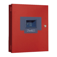
Cabinet Dimensions
Door: 15.342" (38.97 cm) high x 14.677" (37.28 cm) wide x
0.375" (0.95 cm) deep. Backbox: 15.0" (38.10 cm) high x
14.5" (36.83 cm) wide x 3.0" (7.62 cm) deep.
BACKBOX MOUNTINGBACKBOX MOUNTING
BACKBOX MOUNTINGBACKBOX MOUNTING
BACKBOX MOUNTING
The cabinet can be surface mounted. The door is remov-
able during installation by opening and lifting it off the hinges.
The cabinet mounts using two key slots at the top of the
backbox and two additional 0.250" diameter holes at the
bottom.
PRODUCT LINE INFORMATIONPRODUCT LINE INFORMATION
PRODUCT LINE INFORMATIONPRODUCT LINE INFORMATION
PRODUCT LINE INFORMATION
MS-2 Two-zone conventional FACP; 120 VAC, 50/60
Hz, 2.3 A.
MS-2E Same as above with 240 VAC, 50 Hz, 1.15 A
operation.
BB-17F Battery box, required to house two batteries
greater than 7 AH to a maximum of 18 AH.
DP-MS2/4 Dress panel.
MS-2RB MS-2(E) replacement board.
 Loading...