26 FCPS-24FS Series Instruction Manual — P/N 51883:H1 4/14/2011
Trouble Supervision AC Loss Reporting Delay
• With SW1 switch 4 set to the ON position, AC Fail/brownout reporting will be delayed 2 hours
and the following trouble conditions will cause the normally energized Aux. Trouble Relay to
change states regardless of whether the panel is in alarm or standby:
– An AC fail condition at the power supply
– A battery fail condition at the power supply
– A battery charger fail on the power supply
– A ground fault condition on the power supply (zero impedance between the power supply
and ground
– A field wiring fault on the NAC output of the power supply. (If the panel is in alarm, only a
short circuit on the NAC will be detected as a trouble)
• With SW1 switch 4 set to the OFF position, AC Fail/brownout reporting will occur
immediately and the Aux. Trouble Relay will change state only for AC Fail/brownout
conditions. A monitor module can be used to monitor the relay for AC fail.
4.2 AC Loss Reporting Delay
The reporting of AC loss to a central station is usually delayed in order to prevent multiple trans-
missions of AC loss and restoral, thus allowing AC power to stabilize. When a host FACP is pro-
grammed to delay AC loss reporting, the FCPS-24FS must be configured to delay the reporting of
AC fail. This is accomplished by setting SW1 DIP switch 4 to the ON position. This will prevent
AC loss from being reported as a trouble condition for two hours.
Changing the AC Loss Reporting setting will also affect the functioning of the Trouble Relay.
Refer to “Aux. Trouble Relay/AC Fail Relay” on page 25.
Note that the FCPS-24FS power supply will immediately indicate loss of AC power by turning off
the AC Power LED and turning on the Charger Trouble/AC Loss LED, regardless of the setting of
SW1 DIP switch 4.
NOTE: The NAC Trouble LED will indicate which NAC circuit is in trouble by blinking once for
Circuit 1, twice for Circuit 2, three times for Circuit 3 and four times for Circuit 4. If more than one
circuit is in trouble, the LED will blink the highest circuit number in trouble.
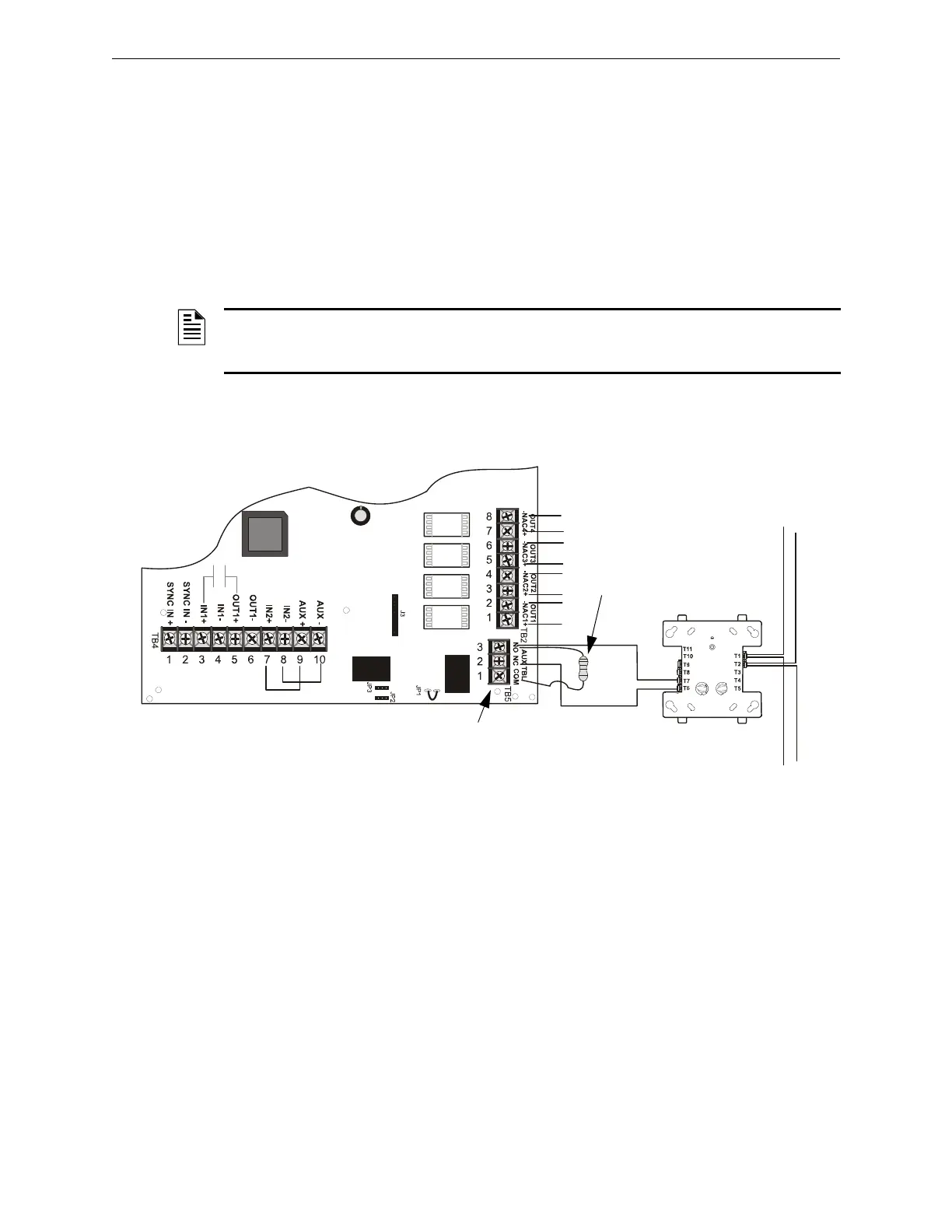
SLC
Monitor Module*
Aux. Trouble Relay
Monitor Module ELR
FCPS-24FS6/8
T7
T6
NO
NC
*If the SLC device does not
match the one in this figure, refer
to the SLC manual wiring con-
version charts for legacy and
newer versions of the modules.