FCPS-24FS Series Instruction Manual — P/N 51883:H1 4/14/2011 35
Master FACP with Slave FCPS-24FS Power Supply Applications
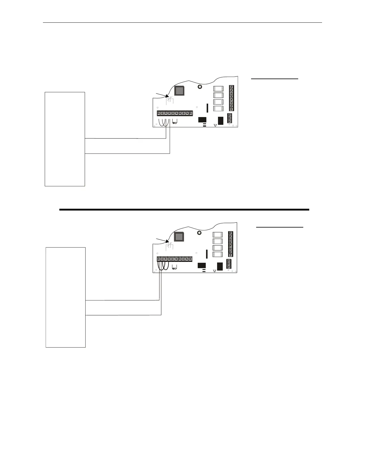
5.5 Master FACP with Slave FCPS-24FS Power Supply
In this application, an FCPS-24FS power supply, configured as a Slave unit, is connected to a mas-
ter FACP programmed for synchronized output. The power supply should be set for synchroniza-
tion which matches the FACP programming.
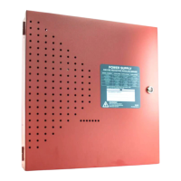
The following notes apply to both illustrations in Figure 5.5 on page 35
1. Refer to NFPA 72, Chapter 4-4, Visible Characteristics, Public Mode.
2. Use only devices from the same manufacturer in each system.
3. If the FACP has a dedicated sync output connector, wire the remote sync output connector to
the FCPS Sync In terminals TB4 terminals 1 & 2. Refer to the Supervised Master/Slave
Connections (Remote Sync Source) in Figure 5.5b.
-
+
TB4
JP3
J3
TB5
TB2
JP1
JP2
OUT4
-NAC4+
OUT3
-NAC3+
OUT2
-NAC2+
OUT1
-NAC1+
AUX -
IN2-
IN2+
OUT1-
OUT1+
IN1-
IN1+
SYNC IN -
SYNC IN +
AUX +
NO NC
AUX TBL
COM
-
+
TB4
JP3
J3
TB5
TB2
JP1
JP2
OUT4
-NAC4+
OUT3
-NAC3+
OUT2
-NAC2+
OUT1
-NAC1+
AUX -
IN2-
IN2+
OUT1-
OUT1+
IN1-
IN1+
SYNC IN -
SYNC IN +
AUX +
NO NC
AUX TBL
COM
Standby Polarity Shown
FCPS-24FS
SW1 Switch Settings
1 & 2 = sync (any setting
but OFF/OFF)
3 = ON (slave)
4 = OFF (no AC Fail
reporting delay)
5 = OFF
6 = OFF
7 = OFF (charger enabled)
8 = OFF (circuit 4 NAC)
Figure 5.5 Supervised Master/Slave Connections
general alarm
24fsapp1c.wmf
See Note 3
24fsapp1b.wmf
SW1 Switch Settings
1 & 2 = sync (any setting
but OFF/OFF)
3 = ON (slave)
4 = OFF (no AC Fail
reporting delay)
5 = OFF
6 = OFF
7 = OFF (charger enabled)
8 = OFF (circuit 4 NAC)
Figure 5.5a: Supervised Master/Slave Connections (Filtered, Synchronized NAC Source)
Figure 5.5b: Supervised Master/Slave Connections (Remote Sync Source)
Standby Polarity Shown
FACP
NAC1
(programmed
for sync)
Internal Trouble
Contact
FACP
Remote Sync
Output
Internal Trouble
Contact