Do you have a question about the Fire-Lite MS-4 and is the answer not in the manual?
Discusses issues with smoke detection, including environmental factors and physical barriers.
Explains heat detector operation and limitations, focusing on property protection.
Covers issues with audible devices (doors, disability) and visual devices (strobes causing seizures).
Details reliance on AC power, battery backup, and proper maintenance.
Emphasizes power disconnection, static sensitivity, and proper component handling.
Covers reacceptance testing after changes and environmental considerations.
Details importance of proper grounding for transient protection.
Includes FCC and Canadian requirements for radio frequency emissions.
Highlights the need to understand AHJ requirements and relevant standards.
Lists relevant NFPA and Underwriters Laboratories standards for compliance.
Mentions NEC articles and local building codes.
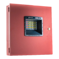
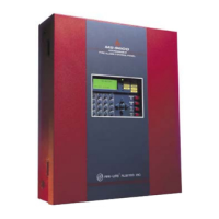
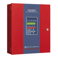
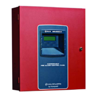
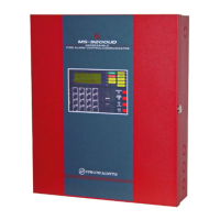
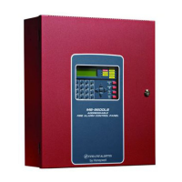
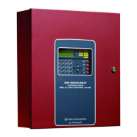
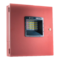
Overview of the MS-2/MS-4 panel's capabilities, zones, and components.
Detailed technical specifications for power, circuits, relays, and components.
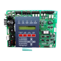
Identifies front panel buttons and status LED indicators.
Describes input/output circuits, piezo sounder, and relays.
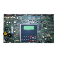
Lists major physical components like the main circuit board and cabinet.
Details optional modules like CAC-4, 4XTMF, 4XZMF, and accessories.
Instructions and dimensions for mounting the FACP cabinet and battery box.
Covers AC primary and battery secondary power sources and connections.
Explains Initiating Device Circuits (IDCs), their configuration, and compatibility.
Details Notification Appliance Circuits (NACs), DC power outputs, and relays.
Specifies rules for separating power-limited and nonpower-limited wiring.
Guides the installation of various optional modules like CAC-4, 4XTMF, etc.
Overview of DIP switch functionality and tables for programming features.
Details programming options for SW1 switches, such as Silence Inhibit and Auto-silence.
Explains SW2 settings for IDC verification and supervisory functions.
Covers SW3 settings for NAC configuration and strobe synchronization.
Describes operation of panel buttons like ACK, Silence, Reset in normal mode.
Explains how to perform audible and silent walktests for system testing.
Details the function and meaning of various status LEDs on the panel.
Describes the panel's behavior in Normal mode and responses to events.
Introduces the four-step process for calculating power supply requirements.
Guides on determining the required AC branch circuit current.
Provides methods for calculating system current for different conditions.
Explains how to calculate required battery capacity based on standby and alarm loads.
| Type | Conventional Fire Alarm Control Panel |
|---|---|
| Number of Zones | 4 |
| Operating Temperature | 32°F to 120°F (0°C to 49°C) |
| Relative Humidity | 10% to 93% non-condensing |
| Operating Voltage | 120 VAC, 60 Hz |
| NAC Circuits | 2 |
| Alarm Relay Contacts | Form-C, rated 2.0 Amps @ 30 VDC (resistive) |
| Trouble Relay Contacts | Form-C, rated 2.0 Amps @ 30 VDC (resistive) |
| Dimensions | 3.5" D |
