Do you have a question about the Fire-Lite MS-9200UD and is the answer not in the manual?
Lists key features like built-in DACT, addressable SLC loop, and device capacity.
Details electrical specifications like AC power, battery, communication loop, and NACs.
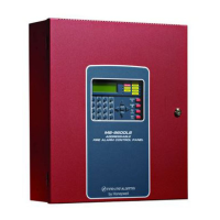
Describes the LCD display, LED indicators, and key panel functions.
Explains SLC communication loop, output circuits, NACs, and relays.
Details the DACT's functions and communication formats.
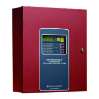
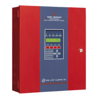
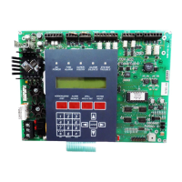
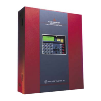
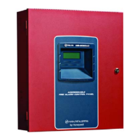
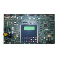
Describes main circuit board, cabinet, transformer, and batteries.
Mentions the 4XTMF transmitter module.
Lists accessories like PK-Plus programming utility and dress panel.
Provides a brief overview of the initial setup steps for the system.
Covers telephone circuit requirements and warnings for the DACT.
Provides instructions for mounting the backbox and circuit board.
Details the procedure for mounting the standard and optional transformers.
Explains AC power, earth ground, and DC power output connections.
Describes the programmable and fixed relays and their contact ratings.
Covers the four NACs and their configuration options.
Explains how to connect for synchronized NAC operation.
Details wiring separation and ferrite bead requirements.
Illustrates the DACT installation and wiring phone jacks.
Instructions for removing the keypad/display and installing modules.
Covers installation of the 4XTMF module for municipal box service.
Explains connecting a serial printer or PC for programming and data.
Details installation of ACM and AFM series annunciators.
Describes using the keypad or computer keyboard for data entry.
Explains the three methods for site-specific programming.
Describes initial programming procedures after device wiring.
Explains how to navigate through programming screens and subscreens.
Covers factory set passwords and how they access programming levels.
Details entering the Master Programming Level for panel configuration.
Explains the Autoprogram feature for quickly bringing devices online.
Allows adding, deleting, or changing programming for addressable devices.
Covers adding, deleting, and editing detector information.
Details the process of adding a new detector to the system.
Explains how to remove an existing detector from the system.
Covers changing existing detector programming.
Allows adding, deleting, or changing programming for modules.
Details the process of adding a new module to the system.
Explains how to remove an existing module from the system.
Covers editing programming for monitor modules.
Covers editing programming for control modules.
Describes configuring zones within the system.
Details how to enable specific zones for system operation.
Explains how to disable specific zones.
Covers special purpose zone programming for PAS and Pre-signal.
Shows a list of all zones programmed into the control panel.
Lists all software zones that are currently enabled.
Lists all software zones that have been disabled.
Explains how to set zone types for reporting purposes.
Displays the available zones that can be programmed.
Allows configuration of the SLC loop for NFPA Style and protocol.
Covers selecting the SLC loop wiring style (4, 6, or 7).
Details the loop protocol settings for SLC operation.
Allows configuration of control panel features like Trouble Reminder and Banner.
Configures an audible reminder for active alarms or troubles.
Allows customization of the LCD display banner text.
Sets the system time, date, and daylight savings.
Instructions for setting the system time.
Instructions for setting the system date.
Configures the clock display format (12/24 hour).
Configures daylight savings time settings.
Allows setting delays for PAS, Pre-signal, and Waterflow.
Sets the delay for Positive Alarm Sequence activation.
Sets the delay for Pre-signal activation.
Sets the delay for waterflow type alarms.
Configures a delay for reporting AC power loss.
Covers programming options for Notification Appliance Circuits.
Details enabling or disabling NAC circuits.
Selects the type of NAC output (Bell, Horn, Strobe, etc.).
Configures NAC circuits for silenceable or nonsilenceable operation.
Sets automatic silencing duration for notification appliances.
Selects coding patterns for NACs.
Assigns zones to NAC circuits.
Configures silence inhibit for NAC circuits.
Selects synchronization type for NACs.
Describes programming options for the panel's relays.
Configures detector sensitivity for Canadian specifications.
Allows silencing of waterflow type circuits.
Checks communication and programming of devices on the SLC loop.
Allows viewing and erasing system events from the history file.
Details how to view specific events in the history file.
Explains how to clear the system's event history.
Allows testing system devices and storing results.
Lists available option modules like annunciators and printer connections.
Covers programming for annunciators and UDACT.
Details programming the integrated Digital Alarm Communicator/Transmitter.
Explains how to enable the onboard DACT.
Configures the primary phone line settings for the DACT.
Configures the secondary phone line settings for the DACT.
Covers programming for the service terminal connection.
Details setting the panel identification number.
Configures phone numbers for service terminal connections.
Sets the number of rings before answering an incoming call.
Configures central station reporting parameters.
Enables or disables central station reporting.
Configures backup reporting options for the DACT.
Sets a limit for DACT trouble calls to prevent runaway dialing.
Details programming primary and secondary central station phone numbers.
Configures the interval for test transmissions to the central station.
Sets the account code for central station communication.
Instructions for entering phone numbers for central station calls.
Selects the communication format for central station reporting.
Lists event codes for various communication formats.
Details how to change master and maintenance passwords.
Explains how to clear system programming and device data.
Allows checking programmed NACs, zones, and I/O correlations.
Describes how to enable or disable individual system points.
Covers viewing and erasing system history events.
Allows checking programming status of NACs and zones.
Explains performing silent or audible walktests.
Details programming the system time and date.
Covers enabling, disabling, and configuring special purpose zones.
Details programming zones 97, 98, and 99 for specific functions.
Describes the function of each panel control button.
Explains how to acknowledge events and step through the display.
Describes silencing alarms and the associated LED indication.
Details the drill function and its effects on NACs and LEDs.
Explains the reset function and its impact on system components.
Describes the function of each status LED on the panel.
Explains the system's behavior during normal, non-alarm conditions.
Describes how the panel indicates and responds to trouble conditions.
Details the panel's response to an alarm condition.
Explains the panel's response to supervisory conditions.
Describes the operation for process monitor conditions.
Details the operation for hazard and tornado conditions.
Explains the operation for medical alert conditions.
Covers the programmable NACs and their operation modes.
Explains assigning devices to software zones.
Describes how to disable or enable input and output points.
Explains the behavior of waterflow circuits.
Covers maintenance alerts, automatic tests, and verification.
Details the system's real-time clock and daylight savings features.
Explains synchronization of notification appliances.
Covers programming coded operation for NAC circuits.
Describes the presignal option for delayed alarm activation.
Explains the Positive Alarm Sequence feature.
Covers special timers like Silence Inhibit and Autosilence.
Prevents Alarm Silence key function for a short period.
Automatically silences notification appliances after a set duration.
Provides audible reminders for alarms and troubles.
Delays activation of waterflow type alarms.
Helps reduce false alarms by verifying smoke detector activations.
Allows testing system devices and storing results.
Allows viewing programmed features and system status.
Displays the status of individual detectors and modules.
Allows viewing zone installation, status, and types.
Displays real-time voltage readings for system components.
Shows if the Trouble Reminder feature is active.
Displays programmed delay times for various functions.
Shows programmed options for Notification Appliance Circuits.
Displays programmed options for system relays.
Checks for unprogrammed NACs, zones, or I/O.
Allows viewing system events stored in the history file.
Displays status of annunciator options and addresses.
Indicates configured phone line dialing methods.
Shows central station reporting status and programming.
Displays panel ID, terminal phone numbers, and ring count.
Shows if the system is configured for a printer or PC.
Allows printing history, walktest logs, or detector data.
Displays daylight savings time settings.
Lists the priority order for transmitting events to central stations.
Details the process of downloading the system program.
Covers secret code verification and data protection.
Explains how to initiate downloads from the control panel.
Details initiating downloads from a remote service terminal.
Explains how to upload data from the control panel to a service terminal.
Outlines the steps for calculating power supply and battery requirements.
Details calculating the required AC branch circuit current.
Explains how to calculate system current draws for different conditions.
Covers calculating the required battery size based on load and standby time.
Explains how input devices are mapped to software zones.
| Type | Addressable Fire Alarm Control Panel |
|---|---|
| Operating Temperature | 32°F to 120°F (0°C to 49°C) |
| NAC Circuits | 4 |
| SLC Loops | 1 |
| Operating Voltage | 24 VDC |
| Battery Charging Current | 1.0 A |
| Number of Notification Appliance Circuits (NACs) | 4 |
| Power Supply | 120 VAC, 60 Hz |
| Battery Backup | 24 VDC |
| Dimensions | 14.5" H x 3.5" D |
| Weight | 11 lbs |
| NAC Current Rating | 2.0 A |
| Relay Contacts | 2 Form C |
| Number of Zones | 198 |
