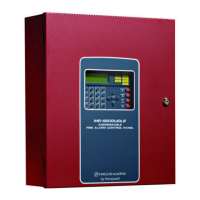
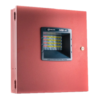
Do you have a question about the Fire-Lite MS-2 and is the answer not in the manual?
Issues affecting smoke detector performance and activation.
Performance aspects and maintenance needs of heat detectors.
Issues with audible/visual alerts and user response.
Limitations related to power sources and component compatibility.
Importance of maintenance to prevent system failure.
Critical warnings about power disconnection and wiring practices.
Recommendations for component handling, grounding, and terminal connections.
Advice on operating environment and system reacceptance testing.
Adherence to FCC and Canadian communication regulations.
Confirmation of adherence to NFPA 72.
List of relevant UL standards for system components.
References to NEC articles and local building codes.
Manufacturer-specific documents for compatibility.
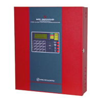
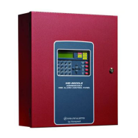
Details the capabilities and applications of both panel models.
Highlights the main functionalities and hardware capabilities of the panels.
Describes LED indicators and programmable NAC features.
Lists available add-on components to enhance system functionality.
Details on AC power input, battery requirements, and charging.
Technical parameters for Initiating Device Circuits (IDCs), Notification Appliance Circuits (NACs), and relays.
Information on resettable and nonresettable power output capabilities.
Describes the function of each button on the control panel's front.
Explains the meaning and behavior of all LED indicators on the panel.
Details the distinct sounds produced by the panel's piezo sounder.
Explains the functionality of IDCs, output power, NACs, and relays.
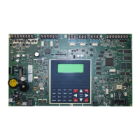
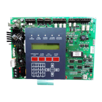
Details the core electronic board and the enclosure.
Information on the power supply components.
Lists available add-on modules and accessories.
Description of the optional battery enclosure.
Information on 411 and 411UD communication modules.
Steps for surface or semi-flush mounting the control panel cabinet.
Connecting primary AC power and ensuring proper grounding.
Connecting and charging secondary batteries.
Description of the panel's IDCs and their capabilities.
Illustrates standard wiring for supervised, power-limited IDCs.
Guide for configuring a zone for both waterflow and supervisory functions.
Explains NAC capabilities and wiring for Class B circuits.
Describes the connections for resettable and nonresettable power.
Explains the function and rating of the panel's relays.
Rules for maintaining distance and separation between wiring types.
Step-by-step guide for installing the CAC-4 module.
Details wiring for Class A circuits using the CAC-4 module.
Covers power, standoffs, and connector alignment for 4X modules.
Details wiring and setup for the 4XTMF's functions.
Explains the relay functions and wiring for the 4XZMF.
Details wiring and connection to the RZA-4XF annunciator.
Identifies the DIP switches and explains their function.
Details features controlled by SW1.
Details features controlled by SW2.
Details features controlled by SW3.
Configuration for alarm silencing behavior.
Configuration for audible/visual signaling patterns.
Configuration for fault notification and AC loss handling.
Configuration for supervisory reset and zone type.
Configuration for detector verification and supervisory monitoring.
Configuration for NAC nonsilenceable and disable features.
Configuration for synchronizing visual notification devices.
Configuration for special waterflow behavior.
Notes the purpose of the spare switch.
Introduction to the panel's primary operating modes.
Description of panel button operations in Normal Mode.
Steps for starting and conducting system walktests.
Details on audible, silent walktests, and how to exit.
Descriptions for AC Power, NAC Disable, and NAC Fault LEDs.
Descriptions for System Trouble, Zone Disable, and Zone Trouble LEDs.
Descriptions for Zone Fire Alarm, Alarm Silence, and Walktest LEDs.
Descriptions for Zone Supervisory, Zone Trouble, and Zone Maintenance LEDs.
Descriptions for Earth Fault, Battery Fault, and Charger Fault LEDs.
Details what indicators are active or off in normal operation.
Actions taken by the panel when a fire alarm is detected.
Steps the panel takes when an alarm condition is cleared.
Actions taken by the panel during a supervisory condition.
Actions when a supervisory condition is cleared.
Details panel actions and indications for trouble events.
Steps taken when trouble conditions are resolved.
Outlines the four-step process for power analysis.
Specifies the dedicated AC power circuit needed for the panel.
Defines terms and methods for calculating current.
Instructions for using the current calculation table.
Table to sum up current draws for different device types.
Using tables to calculate necessary battery capacity.
Required standby and alarm durations according to NFPA standards.
Advice on choosing and installing batteries, including external boxes.
Specifies the warranty period, exclusions, and service.
Limits the manufacturer's responsibility for losses or damages.
| Type | Conventional Fire Alarm Control Panel |
|---|---|
| Number of Zones | 2 |
| NAC Circuits | 2 |
| Operating Temperature | 32°F to 120°F (0°C to 49°C) |
| Power Supply | 120 VAC, 60 Hz, 1.5 A (MS-2) or 220/240 VAC, 50/60 Hz, 0.75 A (MS-2E) |
| Standby Current | 0.1 A |
| Auxiliary Power | 0.5 A |
| Dimensions | 3.5" |
