Installation Power-limited Wiring Requirements
24 MS-2/MS-4 PN 51512:B 08/28/02
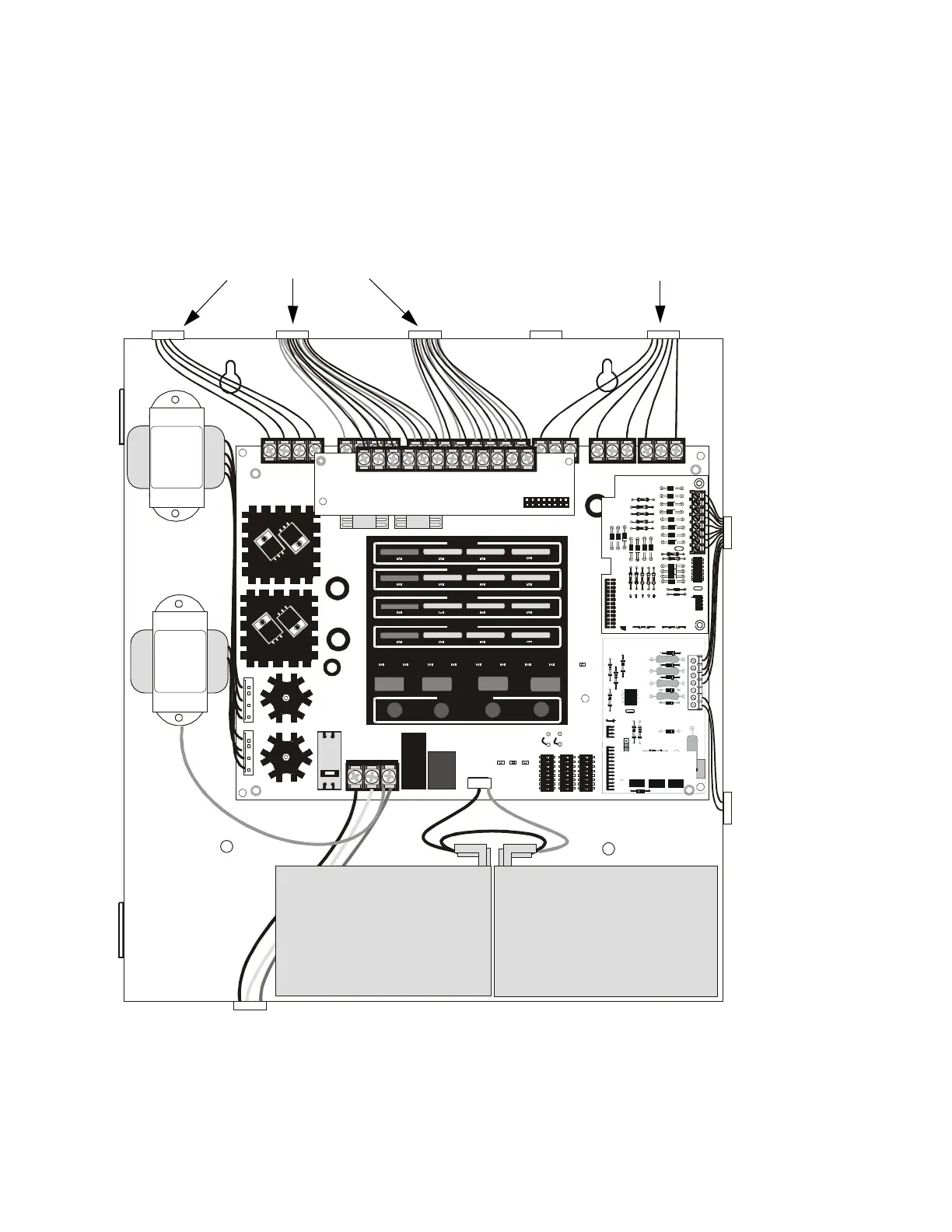
2.5 Power-limited Wiring Requirements
Power-limited and nonpower-limited circuit wiring must remain separated in the
cabinet. All power-limited circuit wiring must remain at least 0.25” (6.35 mm) away
from any nonpower-limited circuit wiring. Furthermore, all power-limited and
nonpower-limited circuit wiring must enter and exit the cabinet through different
knockouts and/or conduits. A typical wiring diagram for the MS-4 is illustrated below.
ON
1 2 3 4 5 6 7 8
ON
1 2 3 4 5 6 7 8
ON
1 2 3 4 5 6 7 8
SUPERVISORY
SUPERVISORY
SUPERVISORY
SUPERVISORY
TROUBLE
TROUBLE
TROUBLE
TROUBLE
MA INTENANCE
MA INTENANCE
MA INTENANCE
MA INTENANCE
FIRE ALARM
FIRE ALARM
AC
POWER
NAC
DI SA BLE
NAC
FA ULT
SYSTEM
TROUBLE
POWER
TROUBLE
WA L K
TEST
ALA RM
SILENCE
ZONE
DI SA BLE
FIRE ALARM
FIRE ALARM
RESET
WALK
TEST
ALARM
SILENCE
ACK
ZONE 1
ZONE 2
ZONE 3
ZONE 4
ZONE
ENABLE/DISABLE
3
4
2
1
TB1
TB2
TB3
TB5
TB6
TB7
+ - + -
Nonreset Resettable
C NC NO
ALARM SUPV
C NC NO
J8
J7
J9
TB8
JP1
SW1
BATTERY
HOT NEUT EARTH
TRANSFORMER 1TRANSFORMER 2
SW2 SW3
JP2
EARTH BATT CHG
4XLB
TB1
A+ A- A+ A-
NAC 1 NAC 2
CLASS A CLASS A
A+ A- A+ A-
ZONE 1 ZONE 2
CLASS A CLASS A
A+ A- A+ A-
ZONE 3 ZONE 4
CLASS A CLASS A
SIGNAL TRANSFORMER
XX-XXX-XXXXXX Rev X
SIGNAL TRANSFORMER
XX-XXX-XXXXXX Rev X
Figure 2.9 Typical UL Power-limited Wiring Requirements
Power-limited Circuits
Nonpower-limited Circuits
Power-limited
Circuits
Nonpower-limited
Circuit
AC Power
4XTMF
4XLMF
CAC-4
ms4ulpwr.cdr