2SWLRQDO0RGXOH,QVWDOODWLRQ ,QVWDOODWLRQ
068'31$
2.9 Optional Module Installation
WARNING! Disconnect all sources of power (AC and DC) before installing or
removing any modules or wiring.
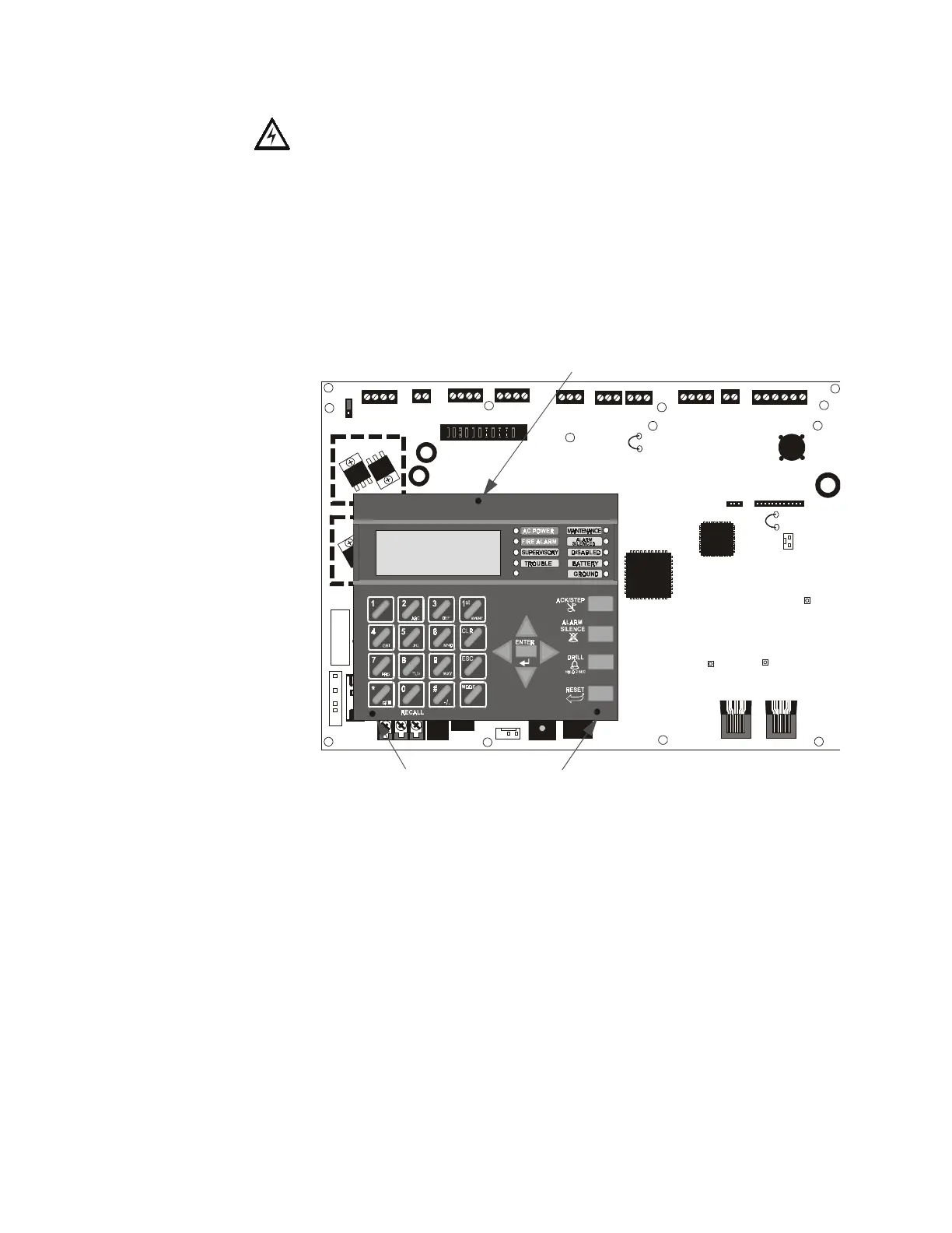
MS-9200UD Keypad/Display Removal
Removal of the keypad/display is normally not necessary. If, however, it becomes
necessary to replace the keypad/display or access jumpers JP5 and JP7 or switch SW1,
the Keypad/Display can be removed by inserting a Phillips screwdriver into each of the
three holes located in the flexible covering of the Keypad/Display and loosening the
three mounting screws. Note that it is not necessary to disconnect the cables between
the Keypad/Display and the main circuit board unless the unit itself is being replaced.
Carefully lift the Keypad/Display and rest the unit at the bottom of the main circuit
board.
+ 24V -
NON- RST
POWER
+ 24V -
RST
POWER
REMOTE PWR
SUPPLY SYNC
NAC 1 CLASS A
NAC 1 & 3 CLASS B
NAC 2 CLASS A
NAC 2 & 4 CLASS B
RELAY 3
RELAY 1
HOT NEUT EARTH
- +
BATTERY
LCD DISPLAY
REMOVE TO
DISABLE GND. FLT.
CUT TO
MONITOR
4XTMF
KISSOFF
PRI. ACTIVE
SEC. ACTIVE
SEC. PHONE LINE
PRI. PHONE LINE
4XTMF
MINI DIN
KEYBOARD CONN.
KEYPAD
I/F
RELAY 2
TRANSFORMER 1
TRAN SFORMER 2
+ -
B+ A + A- B- B+ A+ A- B-
1B+ 3B+ 3B- 1B- 2B+ 4B+ 4B- 2B-
NO NC C
NO NC C NO NC C
B+ A+ B- A - A B
ACS
SHIEL DSLCSLC
SLCSLC
OUT+ IN+ OUT- IN-
TB1
TB2 TB3 TB4 TB7
TB5
TB6
TB8 TB9 TB10
JP4
JP1
JP2
JP3
SW1
JP7
JP5
JP6
1
2
3
1 2 3
TB11
J10
J3
J13 J12
J7
J5
J1
J4
J9
J6
J11
CAUTION!
HIGH VOLTAGE
Figure 2.3 Keypad/Display Removal
Mounting Screw Access Hole
Mounting Screw Access Holes
96dact1.cdr