BALANCED FLUE SITING
The terminal should be positioned to avoid combustion products entering the building or accumulating in
stagnant pockets around buildings. The terminal must be protected by a guard if it is less than 2 metres above
ground level or in a position where any person has access to it (i.e. a balcony). A heat protection shield should be
fitted if the terminal is less than 850mm from a plastic or painted gutter or less than 450mm from painted eaves.
Prevailing winds should be taken into account when siting a flue.
ALWAYS CHECK FOR ANY BUILDING REGULATIONS AMENDMENTS WHICH MAY
HAVE BEEN ISSUED AFTER THE PUBLICATION OF THIS MANUAL
3 3.1 STANDARDS & REGULATIONS - FLUE REGULATIONS
Clearances advised by BS 5410-1: 2014
Regular Appliance (Open, Low Level Discharge and Balanced) Flue Termination Clearance
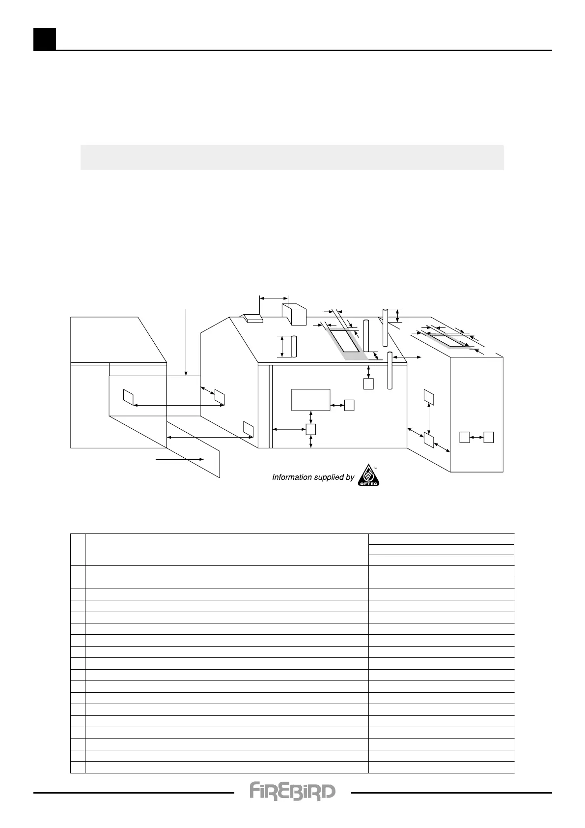
The basic requirement with regard to flue positioning is that no hazard or nuisance is caused by the flue gases.
Diagrams 20a and 20b show clearances advised by BS 5410-1: 2014.
Regional requirements where flue clearances differ can be found in the
regional requirements section in OFTEC Book Four.
A
G
E
B
C & D
K
F
F
L
N
O
P
H
J
Boundary
Boundary
F
Q
Q
Q
Q
Q
Q
Q
R
Pressure JetLocation
Appliance Burner Type
Non Condensing
ROI & NI
A Directly below an opening, airbrick, opening window etc. 600mm
B Horizontally to an opening, airbrick, opening window etc. 600mm
C Below a gutter, eaves or balcony with protection 75mm
D Below a gutter or a balcony without protection 600mm
E From vertical sanitary pipe work 300mm
F From an internal or external corner or surface or boundary alongside the terminal 300mm
G Above ground or balcony level 300mm
H From a surface or a boundary facing the terminal 600mm
J From a terminal facing the terminal 1200mm
K Vertically from a terminal on the same wall 1500mm
L Horizontally from a terminal on the same wall 750mm
M Above the highest point of an intersection with the roof 600mm
N From a vertical structure on the side of the terminal 750mm
O Above a vertical structure less than 750mm from the side of the terminal 600mm
P From a ridge terminal to a vertical structure on the roof 1500mm
Q Above or to the side of any opening on a flat or sloping roof 300mm
R Below any opening on a sloping roof 1000mm
M
Minimum distances to terminals in millimeters as measured from the top of the chimney
or the outer edge of where flue gases pass through low level discharge openings
Diagram 20a
6