Maximum Output . . . . . . . . . . . . . . . . . . . . . . . . . . . . . . . . . . . . . . . . . . . . . . . . . . . . . . . . . . .250 Amps Peak
Output Power Settings . . . . . . . . . . . . . . . . . . . . . . . . . . . . . . . . . . . . . . . . . . . .Seven Position (Rotary Switch)
Wire Speed Adjustment . . . . . . . . . . . . . . . . . . . . . . . . . . . . . . . . . .Infinite Speed Controlled by Potentiometer
Overload Indicator . . . . . . . . . . . . . . . . . . . . . . . . . . . . . . . . . . . . . . . . . . . . . . . . . . . . .Illuminated Pilot Light
Power Switch . . . . . . . . . . . . . . . . . . . . . . . . . . . . . . . . . . . . . . . .Illuminated ON/OFF Switch UL/CSA Listed
Power Cord . . . . . . . . . . . . . . . . . . . . . . . . . . . . . . . . . . . . . . . . . . . . . . . . . . . . . . . . . . . . . . . .10 foot 50 Amp
MIG Gun . . . . . . . . . . . . . . . . . . . . . . . . . . . . . . . . . .10 foot FIREPOWER
®
with ON/OFF Contactor Control
Ground Cable and Clamp . . . . . . . . . . . . . . . . . . . . . . . . . . . . .10 foot Ground Cable 300 Amp Ground Clamp
MIG Gun Connection . . . . . . . . . . . . . . . . . . . . . . . . . . . . . . . . . . . . . . . . . . . . . . . . . . . . . . .Euro Connection
Spool Capacity . . . . . . . . . . . . . . . . . . . . . . . . . . . . . . . . . . . . . . .External Adapter (Installed) 2 lb, 10 lb, 30 lb
Accessories . . . . . . . . . . . . . . . . . . . . . . . . . . . . . . . . . . . . . . . . . . . . . . . . . . . . . . . . . . . . . . . . . . . .Wheel Kit
1 lb. .030 MIG Wire
FIREPOWER
®
Gas Regulator
FIREPOWER
®
MIG Gun
Instruction Manual
MIG-GUN SPECIFICATIONS
Process . . . . . . . . . . . . . . . . . . . . . . . . . . . . . . . . . . . . . . . . . . . . . . . . . . . . . . . . . . .(GMAW/FCAW) Welding
Type of Cooling . . . . . . . . . . . . . . . . . . . . . . . . . . . . . . . . . . . . . . . . . . . . . . . . . . . . . . . . . .Air or Cooling Gas
Duty Cycle
MIG-GUN 10% DUTY 35% DUTY 60% DUTY 100% DUTY
MODEL NO. CYCLE CYCLE CYCLE CYCLE
300 500 amps 450 amps 400 amps 275 amps
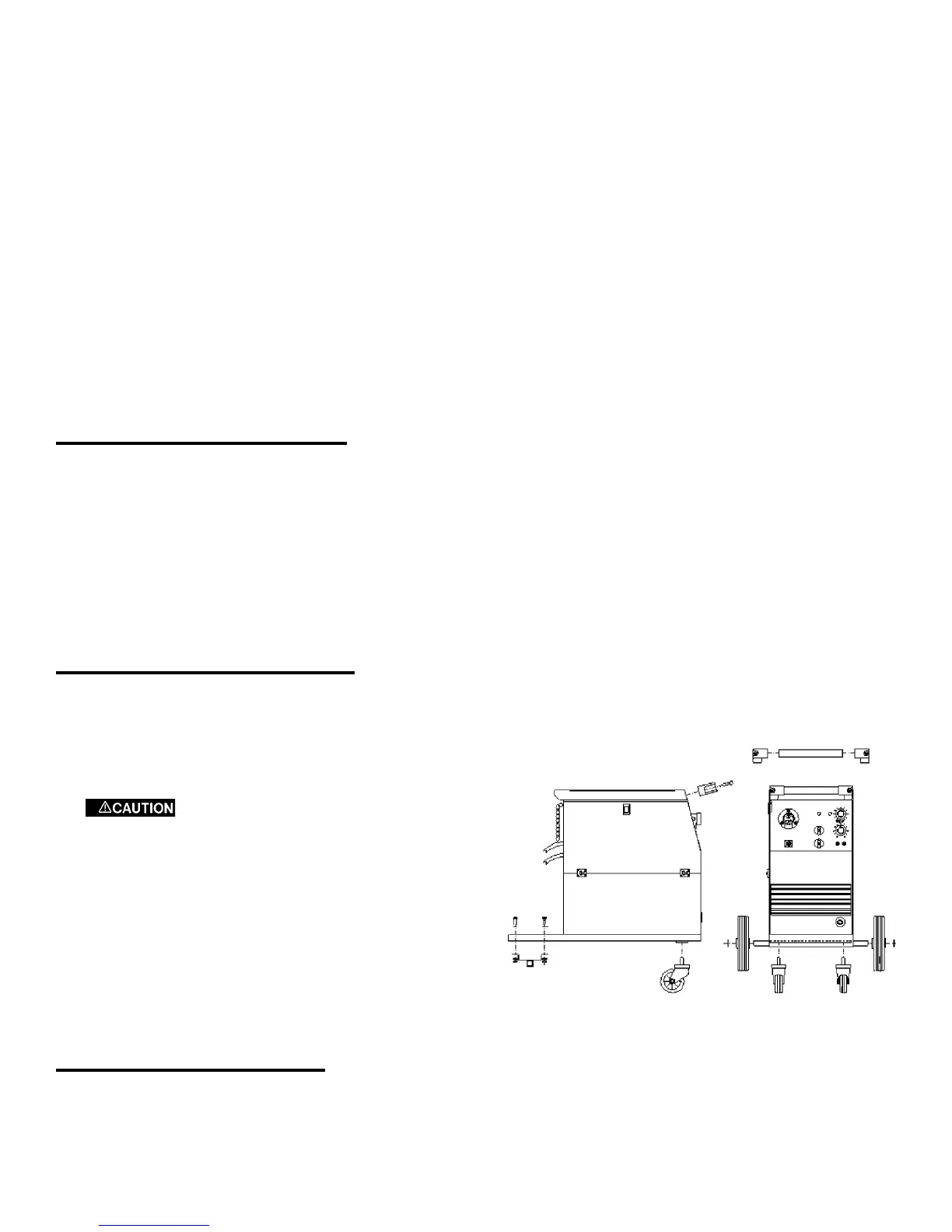
ASSEMBLING THE WELDER
The following steps describe the assembly, installation, maintenance and operations of your new welder.
1. Unpack the welder.
2. Install wheels.
3. Install handle.
Avoid contacts with wires or parts.
DO NOT work with the side panels partially
opened or removed completely from the power
source.
4. Place the power source in a well ventilated area. DO
NOT obstruct the air intake and output vents. A
reduced air flow can cause a reduced duty cycle and
damage internal components.
5. Insure at least 6 feet of open space on each side of the
welder.
MIG GUN INSTALLATION
This unit uses a Firepower MIG Gun furnished with a universal “Euro” connector. The gun is attached to the
matching “Euro” connector on the welder with one threaded fitting.
7
Figure 1: Assembling the Welder