9
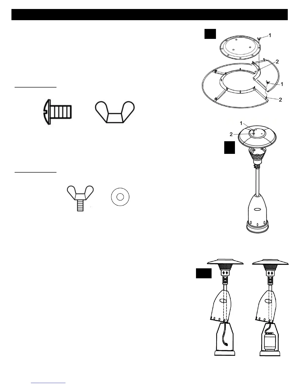
6. Assemble Reflector Panels (B) with Reflector Center Cap (A).
Place two panels side by side. Insert M6x10 Screw into the open holes on
the adjacent panel. Screw on a Wing Nut. Repeat these steps until all
four panels are assembled. Then locate the Reflector Center Cap (A).
Align the holes in the Center Cap with the Screws on each panel and
affix with Wing Nuts to complete assembly.
Assembly Tip: If necessary for proper alignment of reflector sections, loosen each
screw prior to further assembly and retighten after sections are aligned.
Hardware Used: 12 x M6x10 Screw
12 x M6 Wing Nut
7. While supporting heater, tilt the Head Assembly and align the holes in
the Reflector with the holes in the Burner Support Brackets. Slide M6 Washer
over M6x12 Wing Bolt and screw Wing Bolt into the hole on the Burner Bracket.
Repeat for the other two holes. Once you have tightened the Wing Bolts, return
the heater to an upright position.
Hardware Used: 3 x M6x12 Wing Bolt
3 x M6 Washer
8. Connect the regulator to the LP cylinder. The LP cylinder is
sold separately. Use a standard 20 lb. propane cylinder only.
Lift the Tank Housing (E) up and rest it on the top of the assembled
Post Supports (H). Attach Regulator to valve on LP cylinder and hand
tighten securely. Place LP tank onto base of heater and secure LP Tank
on base by hooking Tank Chain (I) onto the Post Support (H). Lower the
Tank Housing.
NOTE: Use this heater only with a propane
vapor withdrawal supply system. See chapter 5 of
the standard for storage and handling of liquefied
petroleum gas, ANSI/NFPA 58. Your local library or
fire department should have this book.