FOR INTERCONNECT: USE #
1SAWG
MINIMUM WIRE
Blinks once a minute
Blinks once a second
- Indicates weak or improperly
connected battery.
9
MAINTENANCE
A.NO
CLEANING
In
addition to weekly testing, this smoke alarm requires yearly battery
replacement and periodic cleaning to remove dust, dirt, and debris.
A.
DANGER: ELECTRICAL
SHOCK
HAZARD. Turn
off
p
owe
r
at
main
servic
e
panel
by
removing
f
use
or
switching
appropriate
circuit
b
reak
er
to
OFF pos
iti
on
before
replacing
b
att
ery
or
clean
i
ng
smoke
alarm.
BATTERY RE
PLACEMENT
Always turn off power to smoke alarm before replacing battery.
Replace battery at least once a year,
or
immediately when the low
battery signal sounds (a chirp once per minute indicates low
battery). On Model ADC, the red LED will blink 4 times per minute
after each low battery chirp. Batteries should be replaced every
year even when the smoke alarm is receiving AC power.
Use only t
he
following batteries
as
replacements
in
this smoke alarm:
Eveready 522 or 1222, Duracell MN 1604, or Ultralife U9V
L-J
A.
WARNING:
DO
NOT
USE
ANY
OTHER
TYPE OF
BATTERY
EXCEPT
AS
SPECIFIED
IN
THIS
MANUAL
.
DO
NOT
USE RECHARGEABLE
BATTERIES.
1.
Turn off power to smoke alarm at main service panel.
2.
Turn smoke alarm counter-clockwise to detach from mounting
plate.
3.
Gently pull down
smoke
alarm. Be careful not to
separa
te
wire connections.
4.
Pull out power plug from back of smoke alar
m.
5. From back
of
smoke alarm, lift tab to open battery pocket door.
6. Remove battery from pocket. Disconnect and discard drained
battery from battery connector.
7.
Connect a fresh, 9-volt battery to connector. The battery will fit
only one way. Be sure battery connector is securely attached to
battery terminals.
8.
Place battery into battery pocket.
9. Close battery pocket door. Push down until it snaps into place.
10. Replace connector plug. Connector will snap into place.
Gently tug connector to be sure it is attached properly.
1
1.
Reattach smoke alarm to mounting plate by turning smoke
alarm clockwise until it snaps into plate.
12. Turn on power and test smoke alarm using Push-to-Test button.
NOTE: If smoke alarms are interconnected, all smoke alarms
should sound an alarm within three seconds after any test
button
is
pushed and the tested smoke alarm sounds.
3.
If smoke alarm does not sound, turn off power at main fuse box
or circuit breaker and check wiring. Retest smoke alarm.
A.
DANGER:
If
al
arm
ho
rn sounds, and smo
ke
alarm
is
not
being te
sted
,
the
s
mok
e ala
rm
is
s
en
si
ng
sm
ok
e.
THE
SOUND
OF
THE
ALA
RM
HORN REQUIRES
YOUR
IMM
EDIATE ATTENTION AND ACTION.
FALSE
ALARM
CONTROLTM
Model ADC features a False Alarm
Control™
that, when activat-
ed, quiets unwanted alarms for up to 15 minutes.
To
use the False Alarm Control™:
Press and release the test button during an unwanted alarm. The
alarm should stop within ten seconds. This means the smoke alarm
is
in False Alarm Control™. For Model ADC
in
an interconnected
system, the red LED on the initiating alarm will continue to blink until
reset by pressing the TEST button.
If
the smoke alarm does not go into False Alarm
Control™
and contin-
ues to sound its loud alarm horn, or if
it
initially goes into False Alarm
Control™
then resounds the alarm, the smoke
is
too heavy and could
be a possibly dangerous
situation-
take emergency action.
• Test each smoke alarm to be sure it is installed correctly and
operating properly.
• Test
all
smoke alarms in an
in
terconnected system after installation.
• The Push-to-Test button accurately tests all functions. DO N
OT
use an open flame to test this smoke alarm. You may ignite and
damage the smoke alarm or your home.
• Test smoke alarms weekly and upon returning from vacation or
when no one has been in the household for sever
al
days.
• Stand at arm's length from the smoke alarm when testing. The
alarm horn is loud to alert you to an emergency and can be
harmful to hearing.
FIELD TESTING IMPORTANT NOTICE:
When testing is required in the field by local inspectors or other par-
ties,
it
should be done using only the Smoke Detector Sensitivity
Analyzer model #5
01
-1 manufactured by Gemini Scientific
Corporation. Follow the Gemini test and set-up instructions provid-
ed by the manufacturer, and use the obscuration limits provided on
the back of the smoke alarm. Refer to the smoke alarm's instruc-
tion manual for maintenance and push-to-test operation.
Test all smoke alarms weekly by doing the following:
1. Observe the green LED. A constant green light indicates the
smoke alarm is receiving 120V AC power.
2.
Firmly depress the Push-to-Test button f
or
at least five (5)
seconds. The smoke alarm will sound a loud beep about four
(4) times a second. On Model ADC, the alarm will sound 2
short reduced-volume beeps, then 1 short loud beep followed
by a pause, then the pattern repeats. The alarm may sound for
up to 10 seconds after releasing the Push-to-Test button.
S
TESTING
THE
SMOKE
ALARM
A
WARNING
....
_-...;:..;;..------------
Blinks 4 times per minute
preceded by an audible chirp
(Interconnected system only):
OFF - another smoke alarm in the network has sensed
smoke and is signalling this alarm.
R E O
ANO
GREEN
LEO
INOICATO
R S
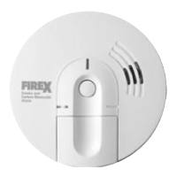
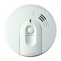
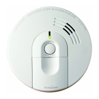
This smoke alarm features separate
red
and green LED indicators.
The LEDs indicate the following:
GREEN
LEO
ON
- AC power
is
present.
OFF - AC power is not present.
REO
LEO
- can be seen through the push to
test button.
- indicating normal operation.
- smoke alarm senses smoke and
simultaneously sounds an audi-
ble alarm.
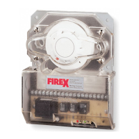
• Use #18 AWG minimum solid or stranded wire. When intercon-
necting, maximum wire length between any two
is
1,500 feet for
#18 AWG or 4,000 feet for
#14AWG
(20 OHMS loop resistance).
• This smoke alarm may be interconnected with as many as
11
other Firex model AD, ADC, FX1218 and PAD smoke alarms,
or as many as 6 Firex model ADH heat alarms for a total of not
more than 18 interconnected devices. DO NOT connect to any
other type
or
model smoke alarm.
• Connect smoke alarms to a single
AC
branch circuit. If local codes
do not permit, be sure the neutral wire
is
common to both phases.
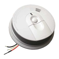
WHITE WHITE
YELLOW
YELLOW
Model ADC only:
Blinks once every 10 seconds - smoke alarm is quieting an
unwanted alarm.
Blinks 3 times per minute - Indicates this unit initiated an
alarm in an interconnected
system (press the
TEST
button
to reset).
7
INTERCO
NNE
CTIN
G
S
MOKE
AL
ARMS
NOT
E:
Smoke alarm will not mount to plate
if
battery
is
not installed.
14. Turn on power at main fuse box or circuit breaker.
15. Test smoke alarm. See TESTING THE SMOKE ALARM.
13. Position smoke alarm to mounting plate and turn clockwise to
lock into place.
(To
engage tamper resist feature, insert pin
into notch on edge
of
smoke alarm after smoke alarm
is
posi-
tioned properly in base. Refer to step #10 on previous page.)
Insert pin here
IJ
 Loading...