Do you have a question about the Fireye InSight 4 Series and is the answer not in the manual?
Suitability of the InSight Series 4 for various combustion applications.
Requirements for periodic proof testing of the safety function as per IEC61508.
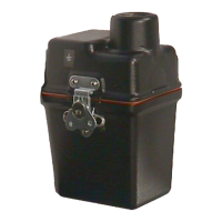
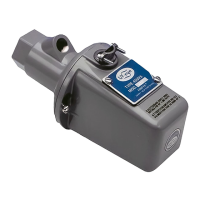
Physical dimensions and mounting details for InSight Series 4 scanners.
Mechanical properties such as housing material, weight, and mounting.
Electrical characteristics including input power, connections, and outputs.
Step-by-step guide for installing the InSight Series 4 scanner.
Precautions and recommendations for scanner cable installation to reduce noise.
Important notes pertaining to wiring diagrams and scanner operation.
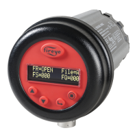
Overview of the keypad and display functions for programming the scanner.
The default display showing current scanner status and operating parameters.
Menu for accessing sub-menus and setpoints for scanner configuration.
Automated process for scanner calibration and setpoint selection.
Menus for manually adjusting scanner setpoints like FFRT and delays.
Indicates the status of the flame relay contacts based on flame quality.
Shows the currently active configuration file (A, B, C, or D).
Represents the intensity of the flame flicker detected by the sensor.
Indicates the perceived quality of the flame, capped at 100.
Displays the status of the learning process for flame detection parameters.
Settings for remote communications using Modbus protocol.
Factory programmed and adjustable thresholds for the flame relay.
Procedure to access the scanner's error history log.
Messages displayed for abnormal operating conditions, with their effects.
Navigation path to enter the scanner's configuration menu.
Requirement for a four-digit password to access configuration menus.
Procedure to modify the existing password for enhanced security.
Steps to disable password protection for easier access during commissioning.
How to select configuration files (Key Pad, Line Inputs, Flame Relay A-B, Modbus).
Time delay setting for automatic switching between File A and File B.
Option to change the user password for accessing configuration menus.
Setting to enable or disable display of warning messages for squelched signals.
Displays the currently active configuration file for editing.
Setting the internal gain range for the IR or UV sensor during AIM.
Access point for copying scanner configuration files between memory locations.
Access point for configuring the 4-20 mA analog output parameters.
Access point for configuring communication settings like Modbus address and baud rate.
Access point for manual configuration of flame relay settings.
Procedure for aiming the scanner and adjusting gain range for optimal signal.
Initiates the learning process for the flame ON condition.
Initiates the learning process for the flame OFF condition.
Manually selecting and editing the active configuration file.
Adjusting the internal gain range for the IR or UV sensor.
Setting the Flame Failure Response Time (FFRT) for the flame relay.
Configuring the ON threshold for the flame relay based on Flame Quality.
Configuring the OFF threshold for the flame relay based on Flame Quality.
Adjusting the sensor gain to optimize flame signal strength.
A record template for saving scanner configuration settings.