Do you have a question about the Fireye InSight 95UVS4-1CEX and is the answer not in the manual?
Equipment can cause severe injury/death; owner responsible for compliance and safe operation.
Requires trained personnel, manual reading, verification; no user serviceable parts.
Isolate power, do not override interlocks, correct faults before operation.
Classified as Type B device per IEC 61508; check UL Online Certification Directory.
Best for applications needing sophistication, flexibility, and remote communications.
Requirement for periodic proof testing of safety functions as a SIL3 capable product.
Active Flame OFF, Active False Flame tests, and alternative steps for critical processes.
Verify flame detection/discrimination by burner cycling; ensure relay de-energizes on flame out.
Warning regarding risk of electrostatic discharge when handling in explosive atmospheres.
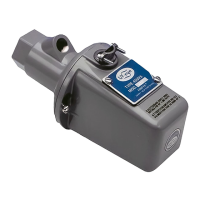
Lists part numbers, sensor types, connector types, and agency approvals.
Details ATEX, DEMKO, IECEx certifications for hazardous locations.
Mount to view primary combustion zone; aim for optimal signal strength.
Avoid ignitor flame detection; ensure unrestricted view by trimming obstructions.
Wear protective filtered lenses when viewing flame due to potential eye damage.
Precautions for hazardous locations: set screw tightening, retainer installation.
Keep cable away from noise sources; use correct 24 Vdc power supply.
Scanner has four files (A, B, C, D) for different operating conditions.
Key Pad, Line Inputs, Flame Relay A-B, or Modbus (Comms) for file selection.
Uses RS485 for remote communication with PC and Fireye software.
Keep cable 12" away, use safety ground, isolate scanner and cooling air.
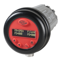
Uses 2-line OLED display and five buttons for navigation and settings.
Access five primary menus via keypad: Main Status, Config, Auto Config, Manual Config.
Default display showing operating status; view error history.
Access sub-menus and setpoints; requires password (default 0205).
Guides calibration: AIM, Learn ON/OFF, gain/bandpass selection.
Allows manual adjustment of FFRT, thresholds, time delays, and other setpoints.
Manages gain (5-255) for signal measurement; affects Flame Quality.
Access error history to view codes, dates, times; reset scanner via PROGRAM key.
Warnings for low/high temperature, IR sensor saturation, and FLAME SIGNAL SET TO 0.
Warnings for FEG out-of-limits or failed light checks.
Warnings for too much IR/UV signal; adjust Gain Range or use orifice.
Press SELECT key to access password entry before configuration.
Procedure for entering or changing the four-digit password.
Four-digit password required for CONFIG menus; default is 0205.
Steps to change the password, including removing protection by setting to "0000".
Set file selection method: Key Pad, Line Inputs, Modbus Comms, Flame Relay.
Options to change password and reset maximum temperature.
Link to access manual configuration for Flame Relay settings.
Change password and reset maximum temperature recorded.
Guides through AIM, Gain Range, Learn ON/OFF for calibration.
Manually configure Flame Relay settings.
Initiates learning Flame ON and Flame OFF conditions for calibration.
Three steps: set gain/AIM, Learn ON, Learn OFF for optimal discrimination.
Aim scanner at primary combustion zone (1/3) for peak signal; adjust Gain Range.
Procedures to learn Flame ON and Flame OFF conditions for scanner calibration.
Optimal gain/bandpass selected after both Learn ON and Learn OFF procedures are performed.
Set FFRT (1-6s); default 1s. >4s violates FM Approval.
Set ON Threshold (5-100) and OFF Threshold (0-95); defaults 40/20.
Set Active File, Gain Range, FFRT, Thresholds, Time Delay, BAND, User Gain, FEG settings.
Configure FFRT, ON/OFF thresholds, and On Time Delay for flame relay control.
Record signal strength at all 21 bands with target flame ON (low fire) and OFF.
Select band yielding best ON/OFF ratio and stability; adjust user gain for thresholds.
Factory defaults ON=40, OFF=20; recommended ON signal >=150.
Verify flame detection/discrimination by burner cycling; ensure relay de-energizes on flame out.
Steps for replacing a damaged scanner using the Configuration Record.
Install scanner, apply power, enter password, and access CONFIG menu.
Input values from Configuration Record into the new scanner.
Initiate "START LEARN ON" via AUTO CONFIG menu.
Turn burner ON/OFF to verify flame detection and discrimination.
| Model | InSight 95UVS4-1CEX |
|---|---|
| Type | UV Scanner |
| Mounting | Threaded connection |
| Approvals | ATEX, IECEx |
| Operating Temperature | -40°C to +70°C (-40°F to +158°F) |
| Spectral Response | 190-290 nm |