EasyManua.ls Logo

Firstech Blade Series - User Manual

Firstech Blade Series
4 pages
Print Icon
To Next Page IconTo Next Page
Loading...
CM-900
CM-900S/900AS
CM7X00
CM7000/7200
Cut loop for A/T
CM900AS/900S Jumper
DEREK ZOOLANDER
Est. 2001
CENTER KIDS
WHO CAN’T READ GOOD
A
N
D
W
H
O
W
A
N
N
A
L
E
A
R
N
T
O
D
O
O
T
H
E
R
S
T
U
F
F
G
O
O
D
T
O
O
I
I
I
I
I
I
I
I
I
I
I
I
I
I
I
I
I
I
I
I
I
I
I
I
I
I
I
I
I
I
I
I
I
I
I
I
I
I
I
I
I
I
I
I
I
I
I
I
I
I
I
I
I
I
I
I
I
I
I
I
I
I
I
I
I
I
I
I
I
I
I
I
I
I
I
I
I
I
I
I
I
I
I
I
I
I
I
I
I
I
I
I
I
I
I
I
I
I
I
I
I
I
I
I
I
I
I
I
I
I
I
I
I
I
I
I
I
I
I
I
I
I
I
I
I
I
for
Green White/BluePark / Auto
I/O Changes
HoodIGN
Lights
CANInstallYearModelMake
BLADE FEATURE COVERAGE
PARKING LIGHTS
SECURE TAKEOVER
GLOW PLUG STATUS
TACH OUTPUT
E-BRAKE STATUS
BRAKE STATUS
RAP SHUTDOWN
DOOR STATUS
DISARM OEM ALARM
ARM OEM ALARM
DOOR UNLOCK
DOOR LOCK
PRIORITY UNLOCK
IMMOBILIZER DATA
Ignition connection.
E
Ignition jumper, NO CONNECTION required.
D
Vehicle hood status ( - ).
C
Not required.
B
Required CAN connections.
A
Firmware: Covered vehicles use either BLADE-AL(DL)-CH8, confirm application, flash module, and update the controller
firmware before installing.
Install: Type 2 vehicles use the included CAN extension cable to source CAN data from the green CAN junction block
(left side of the dash) or from the BCM (pin#25, CANH, brown, pin #26, CANL, yellow).
Lighting: Type B parking lights use the 10-pin connector, secure unused 6-pin connector for safety.
Ignition: Common ignition provisions are listed in the BLADE diagram, ignition is also available at the vehicle BCM
(connector C5/E, pin #27, pink/white).
Hood: Hood status wire is available at the vehicle BCM, connector C1, pin #11 (violet/blue).
FTI-CDP1 - Installation and Configuration Notes
FTI-CDP1 - Vehicle Coverage and Preparation Notes
CONNECT TO PINK.
3500 TIP Start Diesel 2018 Type 2 CJB Type B BCM BCM
DL-CH8
RAM
Question and Answer IconNeed help?

Do you have a question about the Firstech Blade Series and is the answer not in the manual?

Summary

FTI-CDP1 - Vehicle Coverage and Preparation Notes

Firmware Requirements

Covered vehicles use BLADE-AL(DL)-CH8; confirm application, flash module, and update controller firmware.

Installation Guidance

Type 2 vehicles use CAN extension cable to source CAN data from the green CAN junction block or BCM.

Lighting Connections

Type B parking lights use the 10-pin connector; secure unused 6-pin connector for safety.

Ignition Provisions

Ignition is available at the vehicle BCM (connector C5/E, pin #27, pink/white).

Hood Status Wire

Hood status wire is available at the vehicle BCM, connector C1, pin #11 (violet/blue).

FTI-CDP1 - Installation and Configuration Notes

Required CAN Connections

Details regarding required CAN connections for installation.

Unused Connections

Information on connections that are not required.

Vehicle Hood Status Monitoring

Notes on the vehicle hood status function.

Ignition Jumper Configuration

Instruction to connect the ignition jumper to the pink wire.

Ignition Connection Point

Details concerning the ignition connection.

Module Programming Procedure - With KLON

Initial Setup and Button Press

Steps include closing doors, re-opening, and pressing UNLOCK or module programming button.

Key Insertion and Ignition Cycle

Procedure involves turning the key to ON, OFF, START positions and inserting into ignition.

Programming Confirmation and Completion

Monitoring LED status indicators and final procedure completion.

Take Over Procedure - To The Vehicle Owner

Pre-Start Vehicle Requirements

All vehicle doors must be closed and locked prior to remote start sequence.

Vehicle Take Over Steps

Procedure for transferring vehicle control within a 45-second time restriction.

Overview

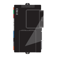
The FTI-CDP1 is a remote start and security interface module designed for specific Dodge/RAM vehicles, particularly the 2018 RAM 3500 TIP Start Diesel. This device, manufactured by FRSTECH, LLC. and utilizing BLADE Series technology from iDatalink, integrates with the vehicle's existing systems to provide remote start functionality and enhanced security features.

Function Description:

The primary function of the FTI-CDP1 is to enable remote starting of the vehicle. It achieves this by interfacing with the vehicle's CAN bus, ignition, and other critical systems. The module also supports various security and convenience features, including:

  • Remote Start: Allows the user to start the vehicle remotely, typically using an aftermarket remote or the OEM remote.
  • Immobilizer Bypass: Bypasses the vehicle's factory immobilizer system during remote start, allowing the engine to turn over. This often involves a "KLON" programming procedure where the module learns the vehicle's key code.
  • Door Lock/Unlock: Integrates with the vehicle's central locking system to provide remote lock and unlock functionality.
  • OEM Alarm Arm/Disarm: Can arm and disarm the vehicle's factory alarm system.
  • Door Status Monitoring: Monitors the status of the vehicle doors.
  • RAP Shutdown: Retained Accessory Power shutdown.
  • Brake Status Monitoring: Monitors the brake pedal status, crucial for safety interlocks during remote start and takeover procedures.
  • E-Brake Status Monitoring: Monitors the electronic parking brake status.
  • Tach Output: Provides an engine RPM signal.
  • Glow Plug Status: Monitors the glow plug status, particularly relevant for diesel vehicles.
  • Secure Takeover: A procedure allowing the user to enter the vehicle and take control after a remote start without the engine shutting off.
  • Parking Lights Control: Controls the vehicle's parking lights.

Important Technical Specifications:

  • Vehicle Compatibility: Specifically designed for the 2018 RAM 3500 TIP Start Diesel. The firmware used is BLADE-AL(DL)-CH8.
  • CAN Bus Integration: The module connects to the vehicle's CAN bus for communication. For "Type 2" vehicles, this involves connecting to the green CAN junction block (left side of the dash) or directly to the BCM (pin #25 for CANH, brown wire; pin #26 for CANL, yellow wire).
  • Ignition Connection: Ignition is available at the vehicle BCM (connector C5/E, pin #27, pink/white wire). A dedicated ignition jumper is used, connected to the pink wire.
  • Hood Status: The hood status wire is available at the vehicle BCM (connector C1, pin #11, violet/blue wire). This is a crucial safety interlock, preventing remote start if the hood is open.
  • Lighting: "Type B" parking lights use a 10-pin connector.
  • Module Type: The device is a "Type 2" installation, indicating specific wiring and integration methods.
  • Power Source: The module requires power (PWR) and ground connections.
  • Immobilizer Data: The module relies on learning immobilizer data from the vehicle's key during programming.
  • LED Indicators: The module uses an LED for programming feedback, flashing different colors (BLUE, RED) and patterns to indicate status or error codes.

Usage Features:

  • Remote Start Activation: Typically initiated by pressing the UNLOCK button on the OEM remote or an aftermarket remote.
  • Takeover Procedure: After a remote start, the user must follow a specific sequence to take control of the vehicle:
    1. Open vehicle door.
    2. Enter vehicle.
    3. Close vehicle door.
    4. Insert key into ignition.
    5. Turn key to ON position.
    6. Press and release BRAKE pedal. This procedure has a time restriction (within 45 seconds) to prevent engine shutdown.
  • Programming Procedure (with KLON):
    1. Close and re-open driver door to wake up the data bus.
    2. Press UNLOCK on OEM remote (or module programming button if no OEM remote).
    3. Wait for LED to flash BLUE once.
    4. Turn key to ON, then OFF.
    5. Wait for LED to turn solid RED.
    6. Remove key.
    7. Insert key into ignition.
    8. Turn key to ON, then START, then OFF.
    9. Wait for LED to flash BLUE, then turn solid BLUE for 2 seconds.
    10. Connect the remote starter (RS) to a computer for extended programming (if applicable).
    11. Disconnect power from the RS and then disconnect the RS from the vehicle.
    12. Module programming is completed.
  • Error Codes: The module's LED flashes RED with specific patterns to indicate programming errors (e.g., 1x for CAN Error, 2x for Key code not learned, 3x for No immobilizer data, 4x for No IGN, etc.).

Maintenance Features:

  • Firmware Updates: It is crucial to confirm the correct application, flash the module, and update the controller firmware before installation to ensure compatibility and optimal performance.
  • Troubleshooting: The LED error codes provide diagnostic information for troubleshooting installation or programming issues.
  • Wiring Diagrams: Detailed wiring diagrams are provided to guide the installer in making the correct connections to the vehicle's OBD-II connector, TIP Start Cylinder, Headlight switch, BCM, and Green Junction Block.
  • Jumper Settings: The module includes jumper settings for various configurations, such as parking light behavior, door trigger input, ignition/starter behavior, and accessory settings.
  • Safety Interlocks: The hood status input and brake status monitoring act as safety interlocks, preventing remote start under unsafe conditions.
  • Professional Installation: Given the complexity of CAN bus integration and immobilizer bypass, professional installation is highly recommended.

Firstech Blade Series Specifications

General IconGeneral
BrandFirstech
ModelBlade Series
CategoryAutomobile Accessories
LanguageEnglish

Related product manuals