Do you have a question about the FISCHER 63298 and is the answer not in the manual?
Guidelines for safe assembly procedures, including protective gear and workspace.
Guidelines for safe operation, including load limits, surface conditions, and user alertness.
Procedure to remove excess air from the hydraulic system for proper operation.
Steps for safely positioning and lifting a vehicle, including safety lock engagement.
Steps for safely lowering a vehicle and disengaging the locking mechanism.
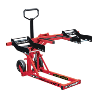
This document outlines the assembly, operation, and maintenance of a hydraulic lift designed for lawnmowers and ATVs. It emphasizes safety precautions throughout, ensuring users are well-informed before, during, and after using the product.
The primary function of this device is to safely lift lawnmowers and ATVs for maintenance, repair, or storage. It operates using a hydraulic ram system, allowing for controlled raising and lowering of vehicles. The lift is designed to support the vehicle by its wheels, providing stable elevation for various tasks.
The assembly process is broken down into several sequential steps, starting with the attachment of the Upper Lift Arm Assembly to the Base. This involves aligning bolt holes and securing components with bolts, flat washers, lock washers, and nuts. Following this, two Support Bars are attached to the Base, ensuring their flat sides align correctly and are secured with similar hardware.
A key step involves attaching the Lower Lift Arm to the Upper Lift Arm Assembly and Support Bars. This requires removing R-Clips and flat washers from the Short and Long Lift Arm Rods. The Lower Lift Arm is then positioned, and the Short Lift Arm Rod is inserted through its bracket and the front of the Lower Lift Arm, secured with a washer and R-Clip. The Support Bars are raised, and the Long Lift Arm Rod is inserted through the Support Bar, the shaft of the Upper Lift Arm Assembly, the rear of the Lower Lift Arm, and the other Support Bar, also secured with a washer and cotter pin.
Next, the Cross Beam is inserted through a bracket on the Upper Lift Arm Assembly and secured with a Cross Beam Pin and R-Clip. Wheel Brackets are then slid over each end of the Cross Beam and secured with Width Pins. Wheel Bracket Rods are inserted through the Wheel Brackets, with R-Clips securing them in place.
The hydraulic Ram is integrated into the lift by inserting the Foot Pedal into its holder on the Ram and securing it with a lock washer and bolt. The Ram is then positioned in the Upper Lift Arm/Shaft Assembly. Lower and Upper Ram Pins, along with washers and R-Clips, secure the Ram to the shaft bracket, clevis base, and Lower Lift Arm bracket.
Finally, the Handle is inserted into its bracket on the Lift Arm/Shaft Assembly and secured with handle bolts, lock washers, and flat washers. The Wheels are attached to the wheel brackets on the rear of the Base using wheel bolts and nuts. Each step is illustrated with diagrams to guide the user through the process, emphasizing proper alignment and secure fastening of all components.
Before operating the lift, it is crucial to bleed the hydraulic system of any excess air, especially before first use or if it appears to be malfunctioning. This involves holding the Release Pedal down and pumping the Foot Pedal quickly several times, then testing the lift without a load.
For lifting, the device must be placed on a flat, level, hard ground surface, away from oncoming traffic. The vehicle's engine should be off, transmission in "PARK" (or lowest gear for manual), and the emergency brake set. Wheels not being lifted should be blocked. The Wheel Bracket supports need to be adjusted to match the vehicle's wheel width, ensuring they are equally distant from the center of the lift to prevent instability. The depth of the Wheel Brackets should also be set slightly larger than the distance between the vehicle wheel and the floor by adjusting the Wheel Bracket Rods.
To prepare for lifting, the Release Pedal is pressed to fully lower the lift. The vehicle's steering should be straightened, and wheel chocks used on the opposite side. The fronts of the Wheel Brackets are then pushed straight against the vehicle's wheels until both wheels rest in the center of the Wheel Bracket.
A critical safety step involves placing the two Safety Lock Levers in the closed, locked position to engage the locking mechanism. Tie-down straps (sold separately) must be used to secure the load to the Tie-Down Bracket. The user then holds the Handle and pumps the Foot Pedal with smooth, full strokes to raise the vehicle. As the load lifts, the locking mechanism automatically engages in one of three positions, which must be confirmed before working on the vehicle.
Lowering the vehicle requires removing all tools and equipment from underneath. The Foot Pedal is pumped slightly to remove weight from the locking mechanism, and the two Safety Lock Levers are placed in the horizontal, unlocked position to disengage the mechanism. The Release Pedal is then slowly pressed to lower the vehicle, keeping clear of the moving parts. Once fully lowered, the tie-down straps are removed, and the lift is moved from under the vehicle. When not in use, the lift should be stored in a safe, dry location out of reach of children.
Regular maintenance is essential for the safe and efficient operation of the lift. Before each use, a general inspection of the lift is required. This includes checking for broken, cracked, or bent parts, loose or missing components, and any other condition that might affect its safe operation. Any identified problems must be corrected before using the lift; damaged equipment should not be used.
Prior to each use, the lift should be thoroughly tested for proper operation. If it appears to be malfunctioning, the bleeding instructions (as described in the usage features) should be followed.
A crucial maintenance task is changing the hydraulic fluid at least once every three years. This procedure involves fully lowering the lift and removing the Fluid Fill Plug on the side of the Ram housing. With assistance, the lift is tipped to completely drain the old hydraulic fluid, which must be disposed of according to local regulations. The Ram housing is then filled with a high-quality hydraulic fluid (not included) until it just begins to run out of the Fluid Fill Hole, after which the Fluid Fill Plug is reinstalled.
For general cleaning, the lift should be wiped with a clean cloth using a detergent or mild solvent. After cleaning and maintenance, the lift should be stored in a safe, dry location, out of reach of children, to ensure its longevity and readiness for future use. Troubleshooting guidance is also provided for common issues such as the jack not lifting its weight, lowering under load, spongy pump stroke, inability to lift all the way, pedal moving up when under load, and fluid leaking from the fill plug. These solutions often involve checking the release pedal, flushing valves, checking and refilling hydraulic fluid, or bleeding the ram. If problems persist, a qualified service technician should be consulted.
| Model | 63298 |
|---|---|
| Brand | FISCHER |
| Minimum Height | 135 mm |
| Type | Jack |
| Capacity | 2000 kg |