Page 5;&(%$*4.8"4,7%<'*#$"&8#=%/7*,#*%4,77%>?@@@?@AA?BCDC1Item 63298
EF;6GHIJ6KFGLIMNFLMG6MFMO6 FEE6NPQH
EF;6GHIJ6KFGLIMNFLMG6MFMO6 FEE6NPQH
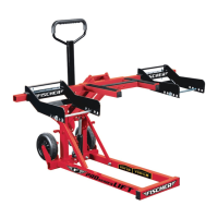
4. Insert Cross Beam (33) through the bracket on the Upper Lift Arm Assembly as shown and align bolt holes.
Insert Cross Beam Pin (36) through center of bracket and Cross Beam.
Secure Cross Beam Pin in place with R-Clip (23).
T//*(%Q"2$%%
F(5%F##*5+7R
O(&##%P*,5%J"8%W^AX
O(&##%P*,5%W^^X
K?O7"/%W\^X
E$*/%]-%%F$$,4.%O(&##%P*,5
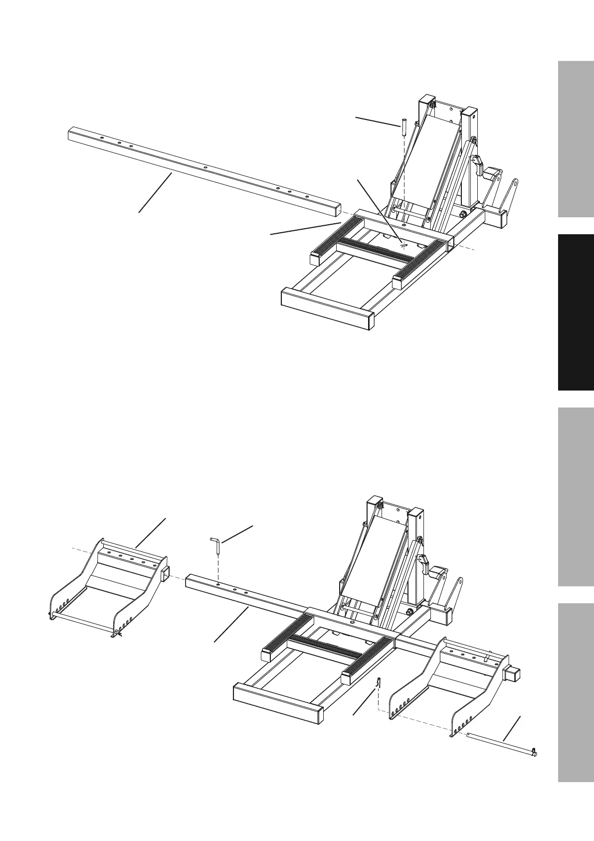
5. Slide one Wheel Bracket (34) over each end of the Cross Beam (33).
Insert Width Pins (31) to secure them in place.
Remove the R-Clip (23) from one end of each Wheel Bracket Rod (32).
Insert one Wheel Bracket Rod through the holes on each Wheel Bracket.
Replace the R-Clip on the end of each Wheel Bracket Rod to secure the Rods in place.
["9$.%J"8%W^>X
[.**7%P(,4Z*$%W^]X
O(&##%P*,5%W^^X
[.**7%
P(,4Z*$%
K&9%W^\X
K?O7"/%
W\^X
E$*/%B-%%L8#$,77%[.**7%P(,4Z*$#%,89%F$$,4.%[.**7%P(,4Z*$%K&9#