Do you have a question about the FISCHER MD-1a and is the answer not in the manual?
Guidance on locating and connecting the Galvanic Unit to a treatment area and power source.
Important warnings regarding high voltage, servicing, and environmental conditions for safe operation.
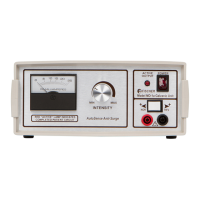
Analog meter displaying actual current flow in DC Milliamperes through the patient circuit.
Selects the meter scale (0-10 or 0-50) for indicating current flow, affecting reading accuracy.
Red LED that illuminates when a completed patient circuit and active current flow are detected.
Rocker-type switch to turn the Galvanic Unit ON or OFF.
Adjusts the desired current level, with actual output indicated on the DC Milliamperes meter.
Allows reversing polarity (NOR/REV) without swapping patient cord plugs (units made after 1/1/2005).
Two banana jacks (RED positive, BLACK negative) for connecting patient cords.
Details including device name, manufacturer, power source, fuse rating, output modes, and voltage/current ranges.
Information on meter accuracy, leakage current limits, and electrical safety certifications.
Device requires minimal maintenance, focusing on regular inspection of the unit and accessories.
Annual inspection covering line cord, plugs, panel controls, and cabinet integrity.
Semi-annual inspection of patient cords, plugs, and electrodes for wear or damage.
Verification of input voltage (105-120 VAC) and reliable ground connection integrity.
Measurement of ground leakage current (chassis/patient) to ensure safety limits are met.
Optional test applying high voltage to check insulation integrity (1250 VAC).
Tests for minimum/maximum output, and verification of meter readings at specified scales (0-10 and 0-50).
Optional measurement of AC ripple in the output current using an oscilloscope (0-0.5 Vpp).
Detailed list of part numbers, item descriptions, and quantities for the MD-1a unit.
Detailed electronic schematic illustrating the internal components and connections of the MD-1a unit.
The FISCHER Model MD-1a Galvanic Unit is a medical device designed for professional use in a clinic setting, offering a versatile approach to galvanic (DC) current applications such as anaphoresis, cataphoresis, or iontophoresis. It generates an adjustable, filtered DC current from standard AC line voltage.
The core function of the MD-1a Galvanic Unit is to provide a controlled direct current for various medical treatments. It features an analog DC Milliammeter that indicates the actual current flow through the connected patient circuit. The unit includes a METER SCALE SWITCH, allowing selection between a 0-10 mA range for more accurate readings of currents less than 10 mA, and a 0-50 mA range. This switch only changes the meter scale, not the output level. An ACTIVE LAMP (red LED) illuminates only when a complete patient circuit is detected and active current is flowing, serving as an indicator of current activation rather than just power-on. The POWER SWITCH turns the unit on and off, with its red top edge exposed when power is on. The INTENSITY KNOB is used to adjust the desired current level, with the actual current indicated on the meter, as its position may vary depending on patient circuit resistance. For units manufactured after January 1, 2005, a POLARITY REVERSAL SWITCH is included, allowing users to switch between normal (red jack positive) and reverse (black jack positive) polarity without swapping patient cord plugs. It is crucial to return the INTENSITY to "0" before changing polarity. Two "banana" OUTPUT JACKS facilitate the connection of patient cords, with the red jack always positive relative to the black (negative) jack. The unit is designed to slowly ramp the output current to its set value once a load resistance is detected, requiring several seconds for stabilization before measurements.
The MD-1a Galvanic Unit is designed for ease of installation and operation. It should be located near a treatment area where controls are easily accessible and plugged into a 110-115 volt A.C. grounded wall receptacle (220-volt operation is available by special order). The use of "cheater" or adapter plugs is strictly prohibited, as proper grounding is essential for safe and proper operation. The unit is equipped with a "hospital grade" plug for reliable grounding. Its light weight and small size make it portable, but proper grounding must always be ensured when relocating. The dual-prong plug of the patient cordset connects to the front panel jacks, with the red jack being positive and the black negative. The accessory electrodes are then firmly plugged into the opposite ends of each cord.
Standard accessories include a Dual Patient Cordset (red and black cords), 3" x 6" Wet pad electrodes, and optionally, Iontophoresis Trays.
Precautions for Use:
The MD-1a Galvanic Unit requires specific periodic maintenance to ensure its continued safe and effective operation. The factory recommends an annual inspection, though maintenance personnel at the installation site may perform inspections at other intervals, not exceeding 24 months.
Visual Device Inspection (Annually):
Visual Electrode Inspection (Every 6 Months):
Electrical Device Inspection (Annually):
Device Output Measurements (Annually):
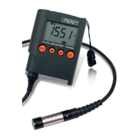
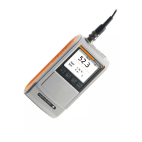
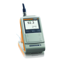
| Type | Coating Thickness Gauge |
|---|---|
| Measurement Range | 0 - 2000 µm |
| Display | LCD |
| Operating Temperature | 0°C to 50°C |
| Measuring principle | Magnetic induction and eddy current |
| Application | Non-destructive coating thickness measurement |
| Resolution | 0.1 μm |
| Probe Type | Integrated probe |
| Power Supply | Batteries |