20
ELECTRICAL CONNECTIONS
US
CA
ELECTRICAL CONNECTIONS RDU MODELS
The electrical supply must be a correctly polarized 120/240 volt, 3-wire
(plus ground), 60 Hz circuit suitable for the maximum current draw of the
model, as detailed in the table below. Please verify your model’s current
draw by checking the rating label on the back of the range.
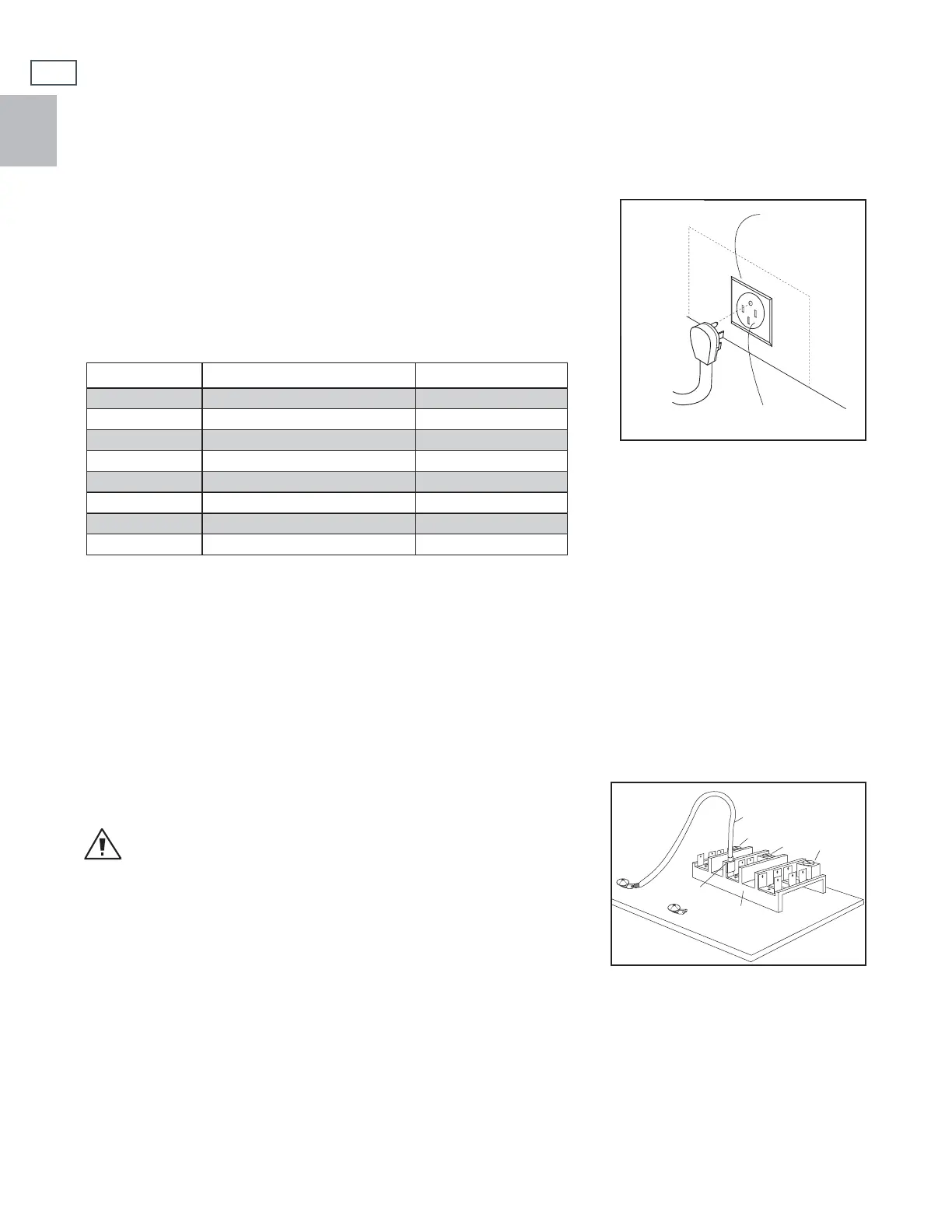
The power receptacle must be a NEMA 14-50 device to accept the four
prong plug supplied with the unit (Fig. 15b). The receptacle should be
located within the area shown in Fig. 12.
REQUIRED GROUNDING METHOD RDU MODELS
This appliance is factory equipped with a power supply cord with a four-prong grounding plug. It must be
plugged into a mating grounding, type receptacle, connected to a correctly polarized 120/240 volt circuit. If
the circuit does not have a grounding type receptacle, it is the responsibility and obligation of the installer to
have the existing receptacle changed to a properly grounded and polarized receptacle in accordance with all
applicable local codes and ordinances by a qualified electrician. In the absence of local codes and ordinances,
the receptacle replacement shall be in accordance with the National Electrical Code.
Note:
The fourth prong (round grounding pin) should not, under any circumstances,
be cut or removed.
WARNING!
The range is equipped for use with an electrical supply which uses a separate
grounding conductor (4 wire system). If this range must be connected
to an electrical system which utilizes a single conductor for ground and
neutral (3 wire system), the grounding jumper at the terminal block must be
connected. The grounding jumper is located behind the front kickpanel.
To connect grounding jumper:
■ Disconnect restraining clip holding jumper.
■ Connect green jumper to open terminal on neutral (white) portion of the terminal block (Fig. 16).
Fig. 15b Connecting the range to the power
supply - RDU Models
Electrical Supply
NEMA 14-50
Receptacle
Line to Range
Connect Here
Red
White
Black
Terminal Block
Green
Fig. 16 RDU terminal block
MODEL MAX. CURRENT DRAW CIRCUIT TO USE
RDU-305
18 amp 30 amp
RDU-364GD
21 amp 30 amp
RDU-364GL
21 amp 30 amp
RDU-366
18 amp 30 amp
RDU-484GG
40 amp 50 amp
RDU-485GD
40 amp 50 amp
RDU-486GD
36 amp 50 amp
RDU-486GL
36 amp 50 amp
 Loading...