Do you have a question about the Fisher & Paykel DD601v2 and is the answer not in the manual?
Covers general safety, electrical safety, ESD, good practices, water isolation, leak checks.
Lists required specialized tools for servicing the product.
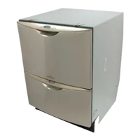
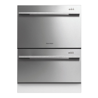
Provides product dimensions and minimum cavity installation sizes.
Lists detailed technical specifications for various internal components.
Details the electronic controller, microcontrollers, and user interface systems.
Describes the motor type, power, speed, and control specifications.
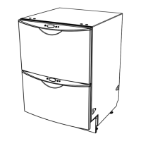
Explains the chassis construction, materials, and drawer front attachment.
Details the cold water inlet, fill process, and detergent/rinse aid dispensing.
Explains the lid seal inflation, function, and deflation during operation.
Describes the tub, rotor, and spray arm functionality within the wash cycle.
Details the heater plate, water heating flow, and overheating control.
Explains the filter plate system and the drain pump operation.
Details the drying cycle operation and the lid seal deflation process.
Explains the function of the lockring nut and the wiring cover.
Introduces fault codes, diagnostic capabilities, and fault display modes.
Details modes like temperature display, rinse aid setup, and tub-open beep.
Covers entering diagnostics, display/download modes, and hardware testing.
Explains running the dishwasher continuously for life testing.
Describes how to retrieve and calculate the appliance's cycle count.
Provides a graphical flowchart for general diagnostic procedures.
Lists fault codes, their displays, descriptions, and possible causes.
Detailed flowcharts for diagnosing specific error codes (F1-F8, U1-U3, performance issues).
Provides a comprehensive diagram of the appliance's internal wiring.
Step-by-step guide for safely removing the drawer front panel.
Instructions for disassembling and removing the handle and LCD display.
Procedure for accessing and removing the drying fan assembly.
Steps for removing the detergent and rinse aid dispenser unit.
Guide for safely disconnecting and removing the main electronic controller.
Instructions for removing both the top and lower kick strips.
Procedure for accessing and removing the main wiring cover.
Steps for removing the main filter plate assembly.
Guide for removing the rotor assembly from the motor.
Detailed instructions for removing the main wash tub.
Procedure for removing the assembly containing the lockring, heater, and motor.
Instructions for lid assembly removal and lid seal replacement.
Procedures for replacing slide runners, front trim, and sound gasket.
Steps for removing the link assembly and the air pump component.
Procedures for removing exhaust valve, water valve, and flood switch.
Instructions for removing the EMI filter and tub microswitch.
| Width | 598mm |
|---|---|
| Height | 410mm |
| Depth | 573mm |
| Energy Rating | 3.5 stars |
| Water Rating | 4.5 stars |
| Noise Level | 44 dBA |
| Drying System | Fan assisted drying |
| Control Type | Electronic |
| Delay Start | Yes |
| Child Lock | Yes |
| Style | Drawer |