EasyManua.ls Logo

Fisher & Paykel V3 DD603 - User Manual

Fisher & Paykel V3 DD603
12 pages
Print Icon
To Next Page IconTo Next Page
Loading...
R
INSTALLATION INSTRUCTIONS
(NOTE: FOR INTEGRATED PANEL PREPARATION INSTRUCTIONS REFER TO SUPPLIED SHEET)
part number 526607 N
05/2005
(page 1 of 12)
US CA
NOTE TO THE INSTALLER
1. Read these instructions completely and carefully.
2. Installation of this DishDrawer
® requires basic
mechanical and electrical skills.
3. Be sure to leave these Instructions with the Customer.
4. At the completion of the DishDrawer
® installation, the
Installer must perform Final Check List as per Section 12
of these Installation Instructions.
5. Remove all packaging materials supplied with the
DishDrawer
®.
6. This dishwasher is manufactured for indoor use only.
NOTE TO THE CUSTOMER
Keep these Installation Instructions with your User Guide
for future reference. The DishDrawer
® must be securely
anchored before it is operated.
WARNING!
Before installing the DishDrawer® , remove the house fuse or open
the circuit breaker. Ensure all water connections are turned OFF. It is
the responsibility of the plumber and electrician to ensure that each
installation complies with all Codes and Regulations.
Important!
These instructions must be followed precisely to ensure correct
venting and operation of the DishDrawer®
. In the event of a fault
related to the incorrect installation, the installer will be liable for any
repairs.
Important!
The DishDrawer® MUST be installed to allow for future removal
from the enclosure if service is required.
Important!
Improper installation is not covered under the Warranty.
Important!
If the DishDrawer® is to be relocated from one installation to
another it must be kept upright to avoid damage from water spillage.
DOUBLE DD603 MODELS
DD603 PREFINISHED (shown left)
DD603 FLAT DOOR (not shown)
DD603I INTEGRATED (shown right)
SINGLE DS603 MODELS
DS603 PREFINISHED (shown left)
DS603 FLAT DOOR (not shown)
DS603I INTEGRATED (shown right)
Question and Answer IconNeed help?

Do you have a question about the Fisher & Paykel V3 DD603 and is the answer not in the manual?

Fisher & Paykel V3 DD603 Specifications

General IconGeneral
Place Settings14
Third RackNo
Water Rating4.5 Stars
Wash ProgramsAuto, Eco, Fast, Gentle, Heavy, Medium, Rinse
Upper Basket FeaturesAdjustable

Summary

Dish Drawer Installation Instructions

Note to the Installer

Read instructions, check skills, leave with customer, perform final check, remove packaging, indoor use only.

Note to the Customer

Keep instructions for reference, secure unit before operation.

Before You Start: Models and Parts

Parts Supplied

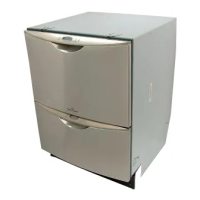
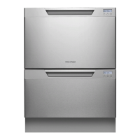
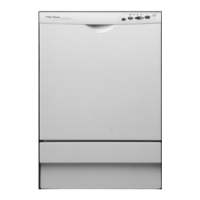
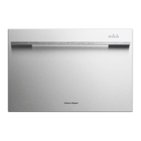
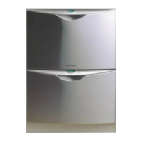
Lists parts supplied for Double and Single DishDrawer models.

Tools Needed

Lists necessary tools for installation of the DishDrawer.

Installation Preparation and Electrical Information

Electrical Preparation

Details requirements for power outlet location and connection options.

Plumbing & Drainage Preparation

Covers water supply valve, pressure limits, and drain hose options.

Cavity Preparation

Recommends sealing cabinetry, applying moisture tape, and ensuring cavity structure.

Power Supply Cord and Grounding

Guidance on power cord handling, damage, and essential grounding instructions.

Double Models Service Specifications

Water Connection and Pressure

Details recommended hot water connection and water pressure requirements.

Drain Connection

Specifies drain hose joiner compatibility for waste tees.

Electrical Connection

Outlines the requirements for the electrical connection (110-120 VAC, 9 Amps).

Length of Services

Provides exit points and lengths for drain hose, inlet hose, and power cord.

The Cavity

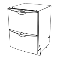
Details cavity dimensions, service hole, mounting tab locations, and toe kick depth.

Double Models Plumbing Options

Option 1: Standpipe with Air Gap

Diagram and explanation for connecting DishDrawer to a standpipe with an air gap.

Option 2: Waste Disposal

Diagram and explanation for connecting DishDrawer to a waste disposal unit.

Option 3: Air Break with Drain Hose Joiner

Diagram and explanation for using an air break with a drain hose joiner.

Single Models Service Specifications

Water Connection and Pressure

Details recommended hot water connection and water pressure requirements.

Drain Connection

Specifies drain hose joiner compatibility for waste tees.

Electrical Connection

Outlines the requirements for the electrical connection (110-120 VAC, 4.5 Amps).

Weight

Specifies the weight of the DishDrawer for Prefinished and Empty states.

Length of Services

Provides exit points and lengths for drain hose, inlet hose, and power cord.

The Cavity

Details cavity dimensions, service hole, mounting tab locations, and toe kick clearance.

Single Models Plumbing Options

Option 1: Standpipe with Air Gap

Diagram and explanation for connecting DishDrawer to a standpipe with an air gap.

Option 2: Waste Disposal

Diagram and explanation for connecting DishDrawer to a waste disposal unit.

Option 3: Air Break with Drain Hose Joiner

Diagram and explanation for using an air break with a drain hose joiner.

Installation Steps

Step 1: Moving the Product into the Cavity

Instructions for safely moving the DishDrawer into its installation cavity.

Step 2: Removing the Tub

Procedure for removing the tub from the DishDrawer unit.

Installation Steps (Continued)

Step 3: Adjusting the Feet

Guide to adjusting the feet for proper leveling of the DishDrawer.

Step 4: Securing the Product

Instructions for securely fastening the DishDrawer to the cabinetry.

Installation Steps (Continued)

Step 5: Electrical Connection

Details on making the electrical connection, including warnings.

Step 6: Refitting the Tub

Procedure for correctly refitting the tub and checking latches.

Installation Steps (Continued)

Step 7: Connecting the Drain Hose

Instructions for connecting the drain hose securely and preventing siphoning.

Step 8: Connecting the Inlet Hose

Guide for connecting the water inlet hose and checking for leaks.

Installation Steps (Continued)

Step 9: Measuring the Toe Kick

Instructions for measuring and marking the toe kick for double models.

Step 10: Trimming the Toe Kick

Procedure for safely trimming the toe kick for double models.

Installation Steps (Final)

Step 11: Fitting the Toe Kick

Instructions for fitting the toe kick to the product for double models.

Step 12: Final Checklist

Comprehensive checklist for ensuring proper installation and operation.

Trouble Shooting

Common issues and their potential solutions during installation.

Step 13: Customer Care

Contact information for Fisher & Paykel Authorized Service Agents.

Related product manuals