EasyManua.ls Logo

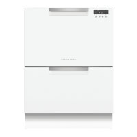
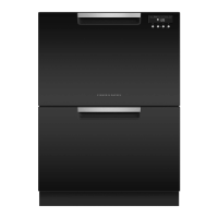
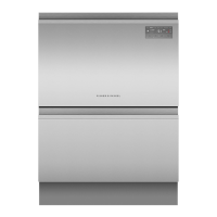
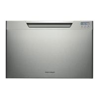
Fisher & Paykel DishDrawer DD60ST 7 User Manual

Fisher & Paykel DishDrawer DD60ST 7
23 pages
To Next Page IconTo Next Page
Page #1 background imageLoading...
Page #1 background image
NZ AU GB IE
590200D 04.13
DD60S 7 & DD60ST 7 models
INSTALLATION INSTRUCTIONS
DishDrawer
TM
dishwasher
Question and Answer IconNeed help?

Do you have a question about the Fisher & Paykel DishDrawer DD60ST 7 and is the answer not in the manual?

Fisher & Paykel DishDrawer DD60ST 7 Specifications

General IconGeneral
BrandFisher & Paykel
ModelDishDrawer DD60ST 7
CategoryDishwasher
LanguageEnglish

Summary

1 FOLLOW THE INSTALLATION SEQUENCE RELEVANT TO YOUR MODEL

Parts Supplied

Lists all components included with the dishwasher for installation.

Product & Cavity Dimensions

Details physical dimensions and required cabinetry space.

Installation Steps

Covers cavity preparation, securing methods, hose/cord distances, and connections.

Final Checks & Troubleshooting

Concludes with final checks and troubleshooting guidance.

2a SAFETY AND WARNINGS - ALL MODELS

Electrical Shock Hazard

Warnings and precautions regarding electrical safety during installation.

Cut Hazard

Warning about sharp edges and potential for cuts during handling.

2b ADDITIONAL SAFETY AND WARNINGS - INTEGRATED MODELS ONLY

Electrical Shock Hazard

Specific electrical safety warnings for integrated models.

3a PARTS SUPPLIED - ALL MODELS

3b ADDITIONAL PARTS SUPPLIED WITH INTEGRATED MODELS

4 PRODUCT DIMENSIONS

5 CABINETRY DIMENSIONS

6a INTEGRATED MODELS WITH REMOTE ONLY - CUSTOM FRONT PANEL CALCULATIONS

Front Panel Specifications

Details specifications for custom front panels for integrated models with remote control.

Width of the Panel

Instructions for calculating the required width of the custom front panel.

Height of the Panel

Instructions for calculating the required height of the custom front panel.

6b INTEGRATED MODELS WITH BADGE ONLY - CUSTOM FRONT PANEL CALCULATIONS

Front Panel Specifications

Details specifications for custom front panels for integrated models with badge control.

Width of the Panel

Instructions for calculating the required width of the custom front panel.

Height of the Panel

Instructions for calculating the required height of the custom front panel.

7 CAVITY PREPARATION

7b INTEGRATED MODELS WITH REMOTE ONLY - PREPARATION FOR EXTERNAL VENTING THROUGH SAME CABINET

7c INTEGRATED MODELS WITH REMOTE ONLY - PREPARATION FOR EXTERNAL VENTING THROUGH ADJACENT CABINET

8 MAXIMUM DISTANCE OF HOSES & CORD FROM CHASSIS EDGE

9 TALL HEIGHT DESIGNER & INTEGRATED MODELS FOR 480 mm CAVITY ONLY - ATTACH CAVITY BRACKET

10a ATTACH SIDE MOUNTING BRACKETS

11g INTEGRATED MODELS WITH REMOTE ONLY - ATTACH VENTING HOSE

12a PULL THROUGH HOSES & MOVE INTO THE CAVITY

13a SECURE THE DRAWER

14a INTEGRATED MODELS WITH REMOTE ONLY - SECURE THE EXTERNAL VENT

10b INTEGRATED MODELS WITH REMOTE ONLY - ATTACH VENTING HOSE

11b PULL THROUGH HOSES & MOVE INTO THE CAVITY

12b REMOVE THE DRAWER

13b SECURE THE DRAWER TO THE CABINETRY

14b REFIT THE DRAWER ONTO THE RUNNERS

15b INTEGRATED MODELS WITH REMOTE ONLY - SECURE THE EXTERNAL VENT

16a REMOVE BRACKET FROM PRODUCT

17a ATTACH PANEL TO PANEL BRACKET

18a EARTH THE PANEL

19a ATTACH PANEL TO PRODUCT

20a ADJUST PANEL HEIGHT TO ALIGN THE CABINETRY GAPS

16b DETERMINE BADGE CUTOUT LOCATION

17b REMOVE BRACKET & DISCONNECT BADGE

18b ROUTE BADGE WIRING THROUGH PANEL

19b ATTACH PANEL TO PANEL BRACKET

20b REATTACH BADGE & EARTH THE PANEL

21b ATTACH PANEL TO PRODUCT

22b ADJUST PANEL HEIGHT TO ALIGN THE CABINETRY GAPS

23 PLUMBING AND DRAINAGE OPTIONS

Standpipe Drainage Setup

Details the plumbing and drainage setup using a standpipe.

Sink Trap Drainage Setup

Details the plumbing and drainage setup using a sink trap and joiner.
24 CONNECT INLET HOSE TO COLD WATER

25 PLUG PRODUCT IN

26 FINAL CHECKLIST

27 TROUBLESHOOTING

Related product manuals