- 1 -
SERVICE
SUMMARY
GWL11 / IWL12
This information is intended for use by individuals possessing adequate experience in servicing electrical, electronic and mechanical appliances. Any attempt to
repair a major appliance may result in personal injury and property damage. The manufacturer or seller cannot be responsible for the interpretation of this
information, nor can it assume any liability in connection with its use.
Cette information est destinée aux personnes possédant l’expérience requise pour réparer des appareils électriques, électroniques et mécaniques. Toute
tentative de réparation d’un gros appareil comporte un risque de blessures à personnes et de dommages matériels. Le fabricant et le revendeur ne peuvent en
aucun cas être chargés de l’interprétation de cette information, ni assumer aucune responsabilité en rapport avec son utilisation.
CAUTION: This machine must be electrically grounded. It can be grounded through the grounding lead in the 3-prong power cord,
if plugged into a properly grounded appliance outlet or through a separate No. 13 or large wire from the cabinet to an established
ground. In all cases the grounding method must comply with any local electrical code requirements. Certain internal parts are
internationally NOT GROUNDED and may present a risk of electrical shock only during servicing. Service personnel do not contact
the following parts while the appliance is energised: Water Valve Brackets, Pump Mounting Bracket. To reduce the risk of shock,
disconnect the power supply cord before servicing.
CAUTION: ALL TERMINALS AND INTERNAL PARTS SHOULD BE TREATED AS LIVE.
IMPORTANT – RE-CONNECT ALL GROUNDING DEVICES.
If grounding wires, screws, straps, clips, nuts or washers used to complete a path to ground are removed for service, they must be
returned to their original position and properly fastened.
ATTENTION : Cette machine doit être mise à la terre. Elle peut l’être par le biais du conducteur de terre du cordon d’alimentation à
prise de terre mâle, s’il est branché sur un point de réseau électrique correctement mis à la terre, ou par le biais d’un fil électrique
épais séparé de l’appareil à la terre. Certaines pièces internes ne sont pas MISES A LA TERRE selon les normes internationales et
peuvent présenter un risque d’électrocution durant l’entretien. Le personnel d’entretien ne doit pas toucher les pièces suivantes
lorsque l’appareil est branché : les supports d’électrovanne et le support de montage de la pompe. Pour réduire le risque
d’électrocution, le cordon d’alimentation doit être débranché avant tout entretien de l’appareil.
ATTENTION : TOUTES COSSES DE CÂBLES ET PIÈCES INTERNES SONT À TRAITER COMME ÉTANT SOUS TENSION
IMPORTANT – REBRANCHER TOUS LES DISPOSITIFS AVEC MISE À LA TERRE
Si les conducteurs de terre, vis, barrettes, clips, écrous ou rondelles utilisés pour acheminer le circuit à la terre sont ôtés lors de
l’entretien, ils doivent être solidement remis à leur place d’origine.
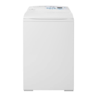
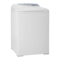
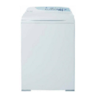
SMART DRIVE TECHNOLOGY
The Smart Drive washer technology is different to
anything you may have seen before.
A brief description follows.
MOTOR CONTROLLER MODULE
This module contains the circuits needed to control
the water valves, pump, water level and rotation of
the motor.
The Pressure Sensor, used to detect the water
level, is part of the Motor Controller Module and
cannot be removed.
DISPLAY MODULE
This receives the inputs from the front panel (i.e.
User settings) and sends the appropriate command
to the Motor Controller Module.
NOTE: Electrostatic Discharge Sensitive
procedures should be observed for all electronic
component handling.
There are no field serviceable parts within the
Motor Controller or Display Module.
MOTOR
The motor is a 3-phase DC brushless motor. The
Motor Controller Module controls rotation of the
motor. Fitted to the Stator (stationary part) is the
Rotor Position Sensor. This detects the position of
the Rotor (moving part) and feeds a signal back to
the Motor Controller Module.
Between the Yellow and Blue connector the
resistance will be 32 ohms. The same resistance
should be measured between the Blue and Red
connector, and also the Yellow and Red connector.
WATER VALVES
The electronics control the water valves so that a
constant wash water temperature is achieved
irrespective of the temperatures and pressures of
the incoming hot and cold water. Two different
valves are used. It is important that the correct
water valve is fitted should they need replacement.
The cold water valve can be identified by the white
(or blue) filter and the hot valve by the yellow (or
red) filter.
IMPORTANTES CONSIGNES DE SÉCURITÉ