This document provides comprehensive installation instructions for the Elba Built-in Oven, specifically covering OB60SC single models for both New Zealand and Australian markets. The manual emphasizes safety, proper installation procedures, and essential checks to ensure the appliance operates correctly and safely.
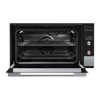
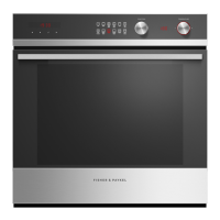
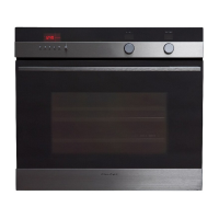
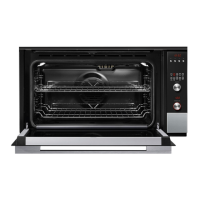
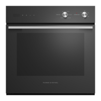
The primary function of this appliance is a built-in oven, designed to be integrated into kitchen cabinetry. It is available in both top-opening and side-opening configurations, with specific dimensions provided for each to facilitate proper installation within various kitchen layouts.
Safety and Warnings
The manual begins with critical safety information, highlighting potential hazards such as electrical shock, fire, and hot surfaces.
- Electrical Shock Hazard: Users are warned to always disconnect the appliance from the mains power supply before any maintenance or repairs. Connection to a good earth wiring system is essential and mandatory. Any alterations to the domestic wiring system must be performed by a qualified electrician. Failure to adhere to these warnings can result in electrical shock or death.
- Fire Hazard: The use of adapters, reducers, or branching devices to connect the appliance to the mains power supply is strictly prohibited, as this can lead to overheating, burning, or fire.
- Hot Surface Hazard: Caution is advised regarding sharp panel edges, as failure to use caution can result in injury or cuts.
Important Safety Instructions for Installation
Several key safety instructions are provided for the installation process:
- To avoid hazards, all instructions must be followed carefully during installation and use.
- The information in this manual should be made available to the installer to potentially reduce installation costs.
- Installation and connection to the mains power supply must only be carried out by a suitably qualified person, adhering to these instructions and all applicable local building and electricity regulations. Incorrect installation can invalidate warranties or liability claims.
- If the power supply cable is damaged, it must be replaced by the manufacturer, its service agent, or a similarly qualified person to prevent hazards.
- An isolating switch providing full disconnection from the power supply, compliant with local wiring rules, must be incorporated into the oven's circuit.
- The oven must be earthed.
Product Dimensions and Cabinetry Requirements
Detailed diagrams and tables are provided for both top-opening and side-opening models, outlining product and cabinetry dimensions in millimeters.
- Product Dimensions (Top Opening Models): This section includes overall height, width, and depth of the product, chassis dimensions, depth of the oven frame and control panel, and the depth of the oven door when fully open. Separate measurements are given for white and stainless steel OB60SC models, noting slight variations in overall depth and depth of the oven frame/control panel.
- Cabinetry Dimensions (Top Opening Models): Specifies minimum inside width, overall width, inside height, overall height, and minimum inside depth of the cavity. A note emphasizes ensuring adequate clearance if a cooktop is installed above the oven, as per the cooktop manufacturer's instructions.
- Product Dimensions (Side Opening Models): Similar to top-opening models, this section details overall height, width, and depth of the product, chassis dimensions, depth of the oven frame and control panel, and the maximum depth of the oven door when fully open.
- Cabinetry Dimensions (Side Opening Models): Provides minimum inside width, overall width, inside height, overall height, and minimum inside depth of the cavity. An important note for side-opening models highlights that doors of adjacent cabinetry may need adjusting to allow the oven door to open properly, recommending a minimum clearance of 2.5mm.
Prior to Installation
Before beginning the installation, several checks are necessary:
- The benchtop and oven cavity must be square, level, and meet the required dimensions.
- The installation must comply with all clearance requirements and applicable standards and regulations.
- A suitable isolating switch, providing full disconnection from the mains power supply, must be incorporated into the permanent wiring. It should be mounted and positioned to comply with local wiring rules and regulations, be of an approved type, and provide a 3mm air gap contact separation in all poles (or in all active conductors if local rules allow).
- The isolating switch must be easily accessible to the customer once the oven is installed.
- There must be at least 1.5m (but not more than 2m) of free power supply cable length within the cavity for ease of installation and servicing.
- If fitted, the oven connection socket must be outside the cavity if the oven is flush to the rear wall.
- The oven must rest on a surface capable of supporting its weight.
- The height from the floor should suit the customer.
- Local building authorities and by-laws should be consulted if there are any doubts regarding installation.
Important Note on Condensation: The manual warns that environmental factors and cooking habits can cause condensation in and around the oven. To protect surrounding cabinetry from potential damage, moisture-proofing the oven cavity is recommended.
Unpacking the Oven
Instructions for unpacking include:
- Do not lift the oven by the door handle.
- Remove the accessories box from the top of the oven and set it aside.
- Remove all packaging and dispose of it responsibly, recycling items where possible.
- Place the unpacked oven onto wooden blocks or similar supports to prevent damage to the lower edge, which is crucial for ventilation and managing excess condensation.
Oven Location (OB60SC Side Opening Models Only)
For side-opening models, specific considerations for oven location are provided:
- Depending on the model, the door can be left- or right-hinged. When determining the oven's location, ensure sufficient space for the door to open fully.
- To access the fixing screw location above the door hinge, the screw/screwdriver needs to be positioned at an angle. Although not recommended, if access at an angle is not possible, the door can be removed first.
- To remove the door: Unscrew the four screws on the inside of the door hinge, carefully remove the door, and lay it on a flat surface. Care must be taken not to damage or scratch the glass.
Electrical Connection
- The oven must be connected to the mains power supply only by a suitably qualified person and must be earthed.
- Before connecting, verify that the domestic wiring system is suitable for the oven's power draw (as specified on the rating plate) and that the voltage matches the value on the rating plate.
- A table provides electrical specifications: Model Code (OB60SC...), Max Power (W) (3000), HZ (50), Voltage (V) (220-240~), and Amps (A) (13).
- A wiring diagram illustrates the connection points for Live (Brown), Neutral (Blue), and Earth (Green & Yellow) wires, emphasizing the need to tighten the cable clamp with a screw.
Securing the Oven to the Cabinetry
- Position the oven in the prepared cavity.
- Do not lift the oven by the door handle.
- Open the oven door fully.
- Mark and pre-drill the screw holes.
- Use the supplied screws to secure the oven to the cabinetry.
- Important: Do not over-tighten the screws. Do not seal the oven into the cabinetry with silicone or glue, as this complicates future servicing. Fisher & Paykel will not cover costs or damage resulting from such removal.
To Replace the Door (if previously removed) for OB60SC Side Opening Models Only:
- Fit the door back onto the hinge and replace the four inner screws.
- Important: Ensure the screws are correctly located and fully tightened. Ensure the door is correctly aligned and gaps around the door are consistent.
Final Checklist
A checklist is provided for the installer to ensure all steps are completed correctly:
- Verify the oven is level and securely fitted to the cabinetry.
- Check that the lower trim is undamaged.
- Open the oven door slowly to its full extent and confirm adequate clearance between the bottom of the door and the lower trim for correct air circulation. If the lower trim is damaged, it should be straightened to ensure the door opens freely.
- Confirm all internal packaging has been removed.
- Ensure all oven vents and openings are clear of any obstruction or damage, as failure to do so can result in poor product performance.
- Verify that the isolating switch is easily accessible to the customer.
Test Operation:
- Turn on the power to the oven. On some models, the display should light up and show "0-00".
- Check the oven's functionality:
- Set the clock (if applicable, refer to the User Guide).
- Select the Bake function and set the temperature to 50°C.
- Wait 10 minutes and confirm the oven has warmed up.
- Switch the oven back off.
- Advise the customer to follow the instructions in their user guide, specifically the 'First use' section.
The manual concludes with a section for recording product details (Model, Serial No., Purchase Date, Purchaser, Dealer Address, Installer's Name, Installer's Signature, Installation Company, and Installation Date) for future reference.

 Need help?
 General



 To Next Page
