Instruction Manual
D200137X012
3570 Positioners
September 2015
29
Key Description Part Number
48 Bias spring, compression type, pl steel
Color Code:
Silver
Light blue
Red
Light green
Brown
49 Service tee, iron
For 3570C only
50 Pipe nipple, pl steel
For 3570C only
51 Pipe tee, iron
For 3570C only
52 Compression plug, brass
For 3570C only (2 req'd)
53 Adaptor, brass
For 3570C only (2 req'd)
54* Cylinder top gauge,
plastic case/brass wetted parts,
For 3570, 3571, 3572, 3576
triple scale, 0‐160 psi/0‐1.1 MPa/0‐11 bar 11B4040X032
dual scale, 0‐160 psi/0‐11 kg/cm
2
11B4040X062
Note
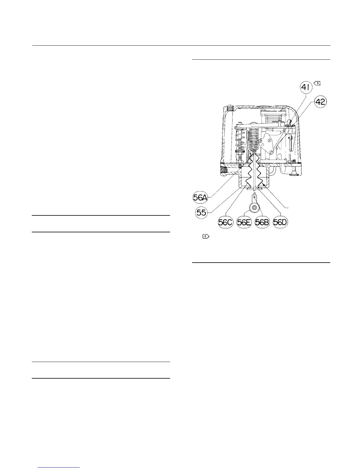
Refer to figure 12 for keys 55 through 26E.
55 Mounting bracket, aluminum
For 3571, 3576, 3577
56A Spring retainer, pl steel
For 3571, 3576, 3577
56B Set screw, pl steel
For 3571, 3576, 3577 (2 req'd)
56C Boot, chloroprene
For 3571, 3576, 3577
56D Spring wire, pl steel
For 3571
For 3576, 3577
56E End bearing
For 3571, 3576, 3577
75 Tubing, copper (specify length)
77 Elbow, 3/8‐inch, brass (specify quantity)
78 Connector, 3/8‐inch brass (specify quantity)
84 Spring retainer spacer, SST
Note
Refer to figure 13 for keys 86 through 101.
86 Spring cap assembly, aluminum and SST
87 Machine screw, pl steel (2 req'd)
88 Torsion spring, steel
89 Extension cover, aluminum
90 Machine screw, pl steel (6 req'd)
91 Positioner cable
Figure 12. Feedback Wire Assembly (Typical with
Fisher 3571, 3576, and 3577 Positioners)
40A9335‐C
A3230
REVERSE BOOT
FOR TRAVELS
OVER 50.8 mm
(2 INCHES)
NOTE:
RELAY BLANK AND SCREWS (KEY 42 AND 42) ARE INSTALLED WHERE SHOWN
FOR 3573 AND 3577 POSITIONERS. FOR 3572 AND 3576 POSITIONERS, THESE
PARTS ARE INSTALLED ON THE OPPOSITE SIDE OF THE POSITIONER
Key Description
92 Actuator cable
93 Cable strap, brass
94 Cap screw, pl steel (3 req'd)
95 Hex nut, pl steel
96 Cable spool, acetal plastic
97 Spring guide, aluminum
98 Warning plate
99 Self‐tapping screw, pl steel
100 Cap screw, pl steel (2 req'd)
101 Positioner extension assembly, aluminum
102 Washer, SST
For 3572, 3576 (1 req'd)
For 3570, 3571, 3573, 3577 (2 req'd)
235 Spring retainer spacer, SST
104.8 mm (4‐1/8 inches) maximum actuator travel,
54.0 mm (2‐1/8 inches) or less valve travel
206.4 mm (8‐1/8 inches) maximum actuator travel,
between 54.0 mm (2‐1/8 inches) and 104.8 mm
(4‐1/8 inches) valve travel (2 different spacers req'd)
206.4 mm (8‐1/8 inches) maximum actuator travel,
less than 54.0 mm (2‐1/8 inches) valve travel (2 req'd)
*Recommended spare parts
 Loading...


