Do you have a question about the Fisher FIELDVUE DLC3010 and is the answer not in the manual?
Details the content covered in the instruction manual for FIELDVUE DLC3010 digital level controllers.
Explains the conventions and terminology used in the manual for Field Communicator operations.
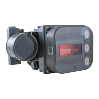
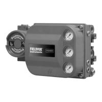
Provides a general description of the DLC3010 digital level controllers and their function.
Describes how to configure the digital level controller before or after installation.
Details steps to protect flexures and parts from damage before moving the sensor and controller.
Provides essential safety warnings and general information for mounting operations.
Refers to specific guidance for installations in hazardous locations.
Explains the methods for mounting the 249 sensor depending on its type.
Specifies the correct orientation for mounting the digital level controller.
Details the procedure for mounting the controller onto a 249 sensor.
Describes mounting considerations for high-temperature environments.
Provides warnings and requirements for electrical connections.
Offers guidance and warnings for field wiring practices.
Explains grounding procedures to prevent static discharge hazards.
Provides recommended grounding techniques for shielded wire.
Details how to make power and current loop connections.
Explains how to connect an RTD for process temperature measurement.
Describes how to connect a Field Communicator for HART communication.
Provides a procedure to change the position of the alarm jumper.
Describes the possible device status conditions: Good, Failed, Maintenance, and Advisory.
Explains the primary variable measurement (level, interface, or density) and its display.
Details how to view identification, distributor, model, and revision information.
Covers initial setup steps for the digital level controller.
Provides guidance on initializing configuration data for proper operation.
Guides the user through the instrument setup process.
Details the procedure to couple the digital level controller to the sensor.
Describes accessing advanced features via the Field Communicator.
Covers entering sensor unit and dimension information.
Permits setting measurement units for displacer length, volume, weight, and torque rate.
Details entering torque tube data, including rate and material.
Specifies whether the instrument is mounted to the right or left of the displacer.
Describes how to view or edit primary variable information.
Details PV value, units, and level offset settings.
Defines the maximum and minimum usable values for range settings.
Allows viewing or editing the upper and lower range values.
Covers viewing or editing process fluid density information.
Details how to view or edit process temperature information.
Allows viewing or editing HART tag, date, descriptor, and serial numbers.
Configures the LCD meter display mode and decimal places.
Covers configuration of primary and temperature alerts.
Details settings for primary variable high and low alerts.
Configures instrument and process temperature alerts.
Covers burst mode and burst option settings.
Enables continuous communication for data transmission.
Selects the variables to be transmitted in burst mode.
Provides an introduction to instrument calibration.
Covers primary calibration procedures.
Recommends calibration procedures based on user input.
Computes sensor gain and offset from two data points.
An accurate method using two independent process conditions.
Calibrates using equivalent weights instead of buoyancy changes.
Sets up nominal calibration using hardware and process information.
Useful when establishing a second data point takes too long.
Captures the current torque tube angle as the input zero reference.
Corrects stored input zero reference assuming gain is accurate.
Covers secondary calibration methods.
Allows trimming the displayed temperature reading.
Trims gain and offset of the digital-to-analog converter.
Adjusts accuracy of output following 4-20 mA commands.
Provides practical examples of calibration procedures.
Describes calibration methods for overweight displacers.
Details calibration for density applications.
Covers calibration when input cannot be varied, using theoretical information.
Explains how to enter theoretical torque tube rates.
Discusses factors affecting measurement accuracy.
Explains sensitivity to fluid density errors in interface applications.
Details applying correction factors for temperature deviations.
Lists and describes active alerts for instrument status.
Describes how to view analog output variables.
Details PV value and % range.
Covers maintenance procedures including tests and resets.
Includes LCD test and loop test procedures.
Procedures for restoring factory defaults or resetting the device.
Explains diagnostic messages displayed on the LCD meter.
Details procedures to verify digital level controller hardware function.
Provides a guide to identify symptoms and corrective actions.
Explains how to use test terminals to measure loop current.
Describes procedures for detaching the controller from the sensor.
Specific steps for removing the controller from a 249 sensor.
Details removal procedures for sensors in high-temperature applications.
Procedure for safely removing the LCD meter assembly.
Procedure for installing a new LCD meter assembly.
Information about the electronics module, including removal and replacement.
Steps to remove the electronics module from the housing.
Steps to install a replacement electronics module.
Information on the terminal box, including removal and replacement.
Procedure for removing the terminal box assembly.
Procedure for installing the terminal box assembly.
Details on removing and replacing the inner guide and access handle assembly.
Information on the lever assembly, including removal and replacement.
Steps to remove the lever assembly from the housing.
Steps to install a replacement lever assembly.
Provides instructions for packing the instrument for shipment.
Instructions on how to order replacement parts.
Lists available mounting kits for various sensors.
Provides a detailed list of parts for the DLC3010.
Details parts included in mounting kits for different sensor types.
Explains the HART protocol for digital communication.
Describes connecting multiple devices to a single line.
Explains how the DLC3010 measures and outputs process variables.
| Manufacturer | Fisher |
|---|---|
| Category | Controller |
| Device Type | Digital Level Controller |
| Communication Protocol | HART |
| Input Signal | 4-20 mA |
| Output Signal | 4-20 mA |
| Power Supply | 24 VDC |
| Operating Temperature | -40 to 85°C (-40 to 185°F) |
| Enclosure Rating | NEMA 4X, IP66 |
| Certifications | ATEX, IECEx |