Do you have a question about the Fisher Fieldvue DVC5010 and is the answer not in the manual?
Covers instrument mounting procedures on the actuator.
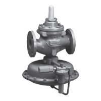
Details mounting methods for the 67CFR filter regulator.
Details how to connect the air supply and gas medium.
Details air supply and pneumatic connections for the instrument.
Explains how to connect the output to the pneumatic actuator.
Describes wiring the 4-20 mA control system loop.
A checklist to verify installation steps are completed.
Explains conduit and loop wiring for electrical connections.
Specifies pressure connection types and tubing size.
Configures the instrument using automated procedures and wizards.
How to connect the HART communicator to the digital valve controller.
Procedure to automatically calibrate the valve's travel range.
Allows manual configuration of instrument parameters.
How to determine and configure travel sensor rotation.
Adjusting tuning sets to improve valve stability or responsiveness.
Provides access to a comprehensive set of configuration options.
Procedures for calibrating instrument travel and pressure sensors.
Commands for moving the valve to specific positions or sequences.
Describes maintenance procedures for the master module.
| Manufacturer | Emerson |
|---|---|
| Category | Controller |
| Type | Digital Valve Controller |
| Operating Temperature | -40 to 85°C (-40 to 185°F) |
| Enclosure Rating | NEMA 4X, IP66 |
| Hazardous Area Certifications | ATEX, IECEx, FM, CSA |
| Communication Protocols | HART |
| Input Signal | 4-20 mA |
| Mounting | Direct mounting on valve |
| Certifications | CE |


 Loading...