DVC5000 Series
November 1999
4-2
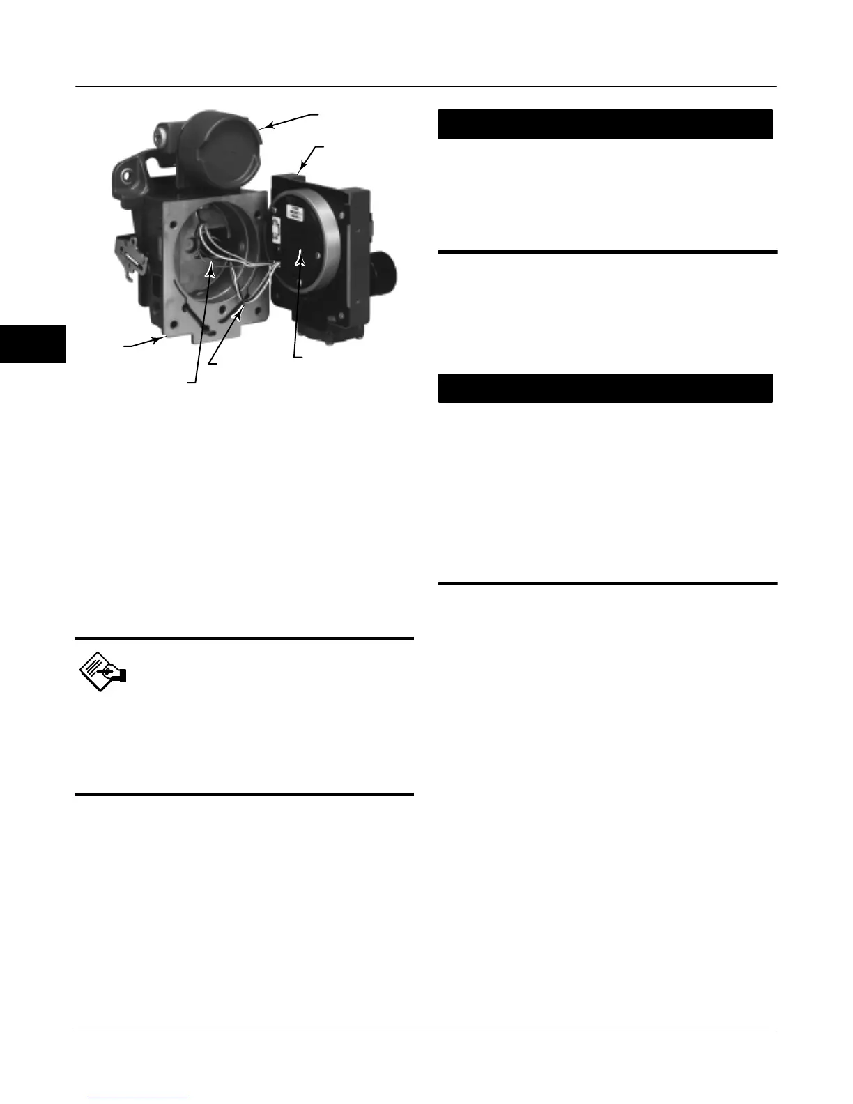
Figure 4-2. Printed Wiring Board Cable Connections
TERMINAL BOX
MODULE BASE
ASSEMBLY
PRINTED WIRING
BOARD ASSEMBLY
HOUSING
CABLE TO
TERMINAL BOX
W7654 / IL
CABLE TO
TRAVEL SENSOR
2. Unscrew the captive screw in the cover and
remove the cover from the module base.
3. Using a 5/16-inch hex wrench, loosen the
four-socket head screws. These screws are captive in
the module base by retaining rings.
Note
The master module is linked to the hous-
ing by two cable assemblies. Disconnect
these cable assemblies after you pull the
master module out of the housing.
4. Pull the master module straight out of the housing.
Once clear of the housing, swing the master module to
the side of the housing to gain access to the cable
assemblies.
5. The digital valve controller has two cable
assemblies, shown in figure 4-2, which connect the
master module, via the printed wiring board assembly,
to the travel sensor and the terminal box. Disconnect
these cable assemblies from the printed wiring board
assembly on the back of the master module.
CAUTION
To avoid affecting performance of the
instrument, take care not to damage
the master module gasket or guide
surface. Do not bump or damage the
bare connector pins on the printed wir-
ing board assembly.
Replacing the Master Module
To replace the master module, perform the following
steps. Refer to figure 4-1.
CAUTION
To avoid affecting performance of the
instrument, inspect the guide surface
on the module and the corresponding
seating area in the housing before
installing the module base assembly.
These surfaces must be free of dust,
dirt, scratches, and contamination.
Ensure the gasket is in good condi-
tion. Do not reuse a damaged or worn
gasket.
1. Ensure the gasket is aligned properly on the
master module.
2. Connect the terminal box connector to the printed
wiring board assembly. Orientation of the connector is
required.
3. Connect the travel sensor connector to the pwb
assembly. Orientation of the connector is required.
4. Insert the module base into the housing.
5. Insert the four socket head screws in the master
module into the housing. If not already installed, press
four retaining rings into the module base. Evenly
tighten the screws in a crisscross pattern to a final
torque of 138 lbfSin (16 NSm).
6. Insert the cover hinge tabs into the module base.
Swing the cover down into position and tighten the
cover screw.
In the next two steps, refer to figure 2-2.
7. If not already installed, screw the vent into the vent
connection on the back of the housing.
8. If not already installed, apply sealant to the pipe
plug and install it in the output connection on the back
of the housing.
4

 Loading...


