Initial Setup and Calibration
November 1999
3-3
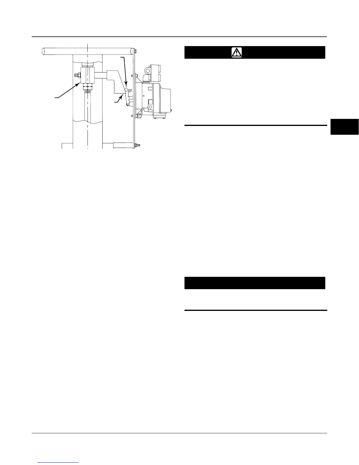
Figure 3-3. Feedback Connection for
Model 471 Sliding-Stem Actuator
CAM
ROLLER
27B6708-B
E0032 / IL
STEM
CONNECTOR
After the Setup Wizard completes the setup, press OK
to return to the Auto Setup menu. Select Auto Calib
Travel to automatically calibrate the instrument travel.
Follow the prompts on the HART Communicator
display. The calibration procedure uses the valve and
actuator stops as the 0% and 100% calibration points.
For additional information, refer to Auto Calibrate
Travel in this section.
Other Mountings
If the actuator on which the instrument is mounted is
not listed by the Setup Wizard, specify OTHER as the
actuator manufacturer or actuator type. You are then
prompted for setup parameters such as:
D Actuator Type (single-acting or double-acting)
D Valve Style (rotary or sliding-stem)
D Feedback Connection (Rotary - All, SStem -
Standard, SStem - Roller). For rotary valves, enter
Rotary - All. For sliding-stem valves, if the feedback
linkage consists of a connector arm, adjustment arm,
and feedback arm (as shown in figure 3-4), enter
SStem - Standard. If the feedback linkage consists of
a roller that follows a cam (as shown in figure 3-3),
enter SStem - Roller.
D On Loss of Instrument Signal, Valve (opens
or closes) This identifies whether the valve is fully
open or fully closed when the input is 0%. If you are
unsure how to set this parameter, disconnect the
current source to the instrument. (With direct acting
digital valve controllers, disconnecting the current
source is the same as setting the output pressure to
zero.)
WARNING
If you answer YES to the prompt for
permission to move the valve, the in-
strument will move the valve through
a significant portion of its travel
range. To avoid personal injury and
property damage caused by the re-
lease of pressure or process fluid,
provide some temporary means of
control for the process.
D Travel Sensor Motion (increasing air pressure
causes the travel sensor shaft to rotate clockwise or
counterclockwise), The Setup Wizard asks if it can
move the valve to determine travel sensor motion. If
you answer yes, the instrument will stroke the valve
the full travel span to determine travel sensor motion.
If you answer No, then you must specify the rotation
for increasing air pressure: clockwise or counterclock-
wise. Determine rotation by viewing the end of the
travel sensor shaft, as shown in figure 3-4. If
increasing air pressure to the actuator causes the
shaft to turn clockwise, enter CW (clockwise). If it
causes the shaft to turn counterclockwise, enter CCW
(counterclockwise).
D Instrument Supply Pressure Range. This
adjusts the range of the instrument pressure sensor.
Supply Pressure is configured in pressure units of psi,
bar, or kPa. Select a supply pressure range that
includes the instrument supply pressure.
CAUTION
Changes to the tuning set can result in
valve/actuator instability.
D Tuning Set There are eleven tuning sets to
choose from. Each tuning set provides preselected
values for the digital valve controller gain and rate
settings. Typically, tuning set C provides the slowest
response and M provides the fastest response. For
smaller actuators, use tuning set C or D. For larger
actuators , use tuning set F or G.
After the Setup Wizard completes the setup, press OK
to return to the Auto Setup menu. Select Auto Calib
Travel to automatically calibrate the instrument travel.
Follow the prompts on the HART Communicator
display. The calibration procedure uses the valve and
actuator stops as the 0% and 100% calibration points.
For additional information, refer to Auto Calibrate
Travel in this section.
3

 Loading...


