Instruction Manual
D102748X012
Installation
October 2014
22
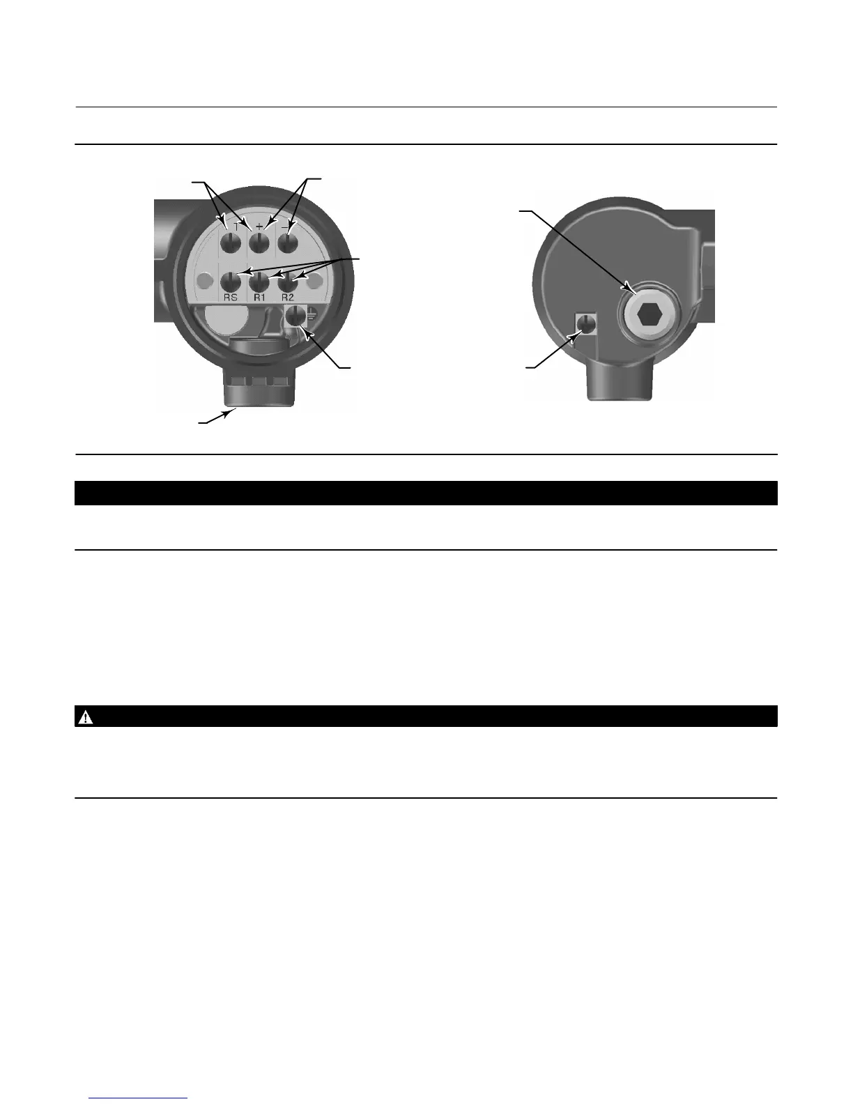
Figure 2‐11. Digital Level Controller Terminal Box
4‐20 mA LOOP
CONNECTIONS
TEST CONNECTIONS
INTERNAL
GROUND
CONNECTION
1/2 NPT
CONDUIT
CONNECTION
FRONT VIEW
REAR VIEW
RTD
CONNECTIONS
W8041
EXTERNAL
GROUND
CONNECTION
1/2 NPT
CONDUIT
CONNECTION
CAUTION
Do not apply loop power across the T and + terminals. This can destroy the 1 Ohm sense resistor in the terminal box. Do not
apply loop power across the Rs and — terminals. This can destroy the 50 Ohm sense resistor in the electronics module.
When wiring to screw terminals, the use of crimped lugs is recommended. Tighten the terminal screws to ensure that
good contact is made. No additional power wiring is required. All digital level controller covers must be fully engaged
to meet explosion proof requirements. For ATEX approved units, the terminal box cover set screw must engage one of
the recesses in the terminal box beneath the terminal box cover.
Grounding
WARNING
Personal injury or property damage can result from fire or explosion caused by the discharge of static electricity when
flammable or hazardous gases are present. Connect a 14 AWG (2.1 mm
2
) ground strap between the digital level controller
and earth ground when flammable or hazardous gases are present. Refer to national and local codes and standards for
grounding requirements.
The digital level controller will operate with the current signal loop either floating or grounded. However, the extra
noise in floating systems affects many types of readout devices. If the signal appears noisy or erratic, grounding the
current signal loop at a single point may solve the problem. The best place to ground the loop is at the negative
terminal of the power supply. As an alternative, ground either side of the readout device. Do not ground the current
signal loop at more than one point.
Shielded Wire
Recommended grounding techniques for shielded wire usually call for a single grounding point for the shield. You can
either connect the shield at the power supply or to the grounding terminals, either internal or external, at the
instrument terminal box shown in figure 2‐11.
 Loading...


