Instruction Manual
D102748X012
Installation
October 2014
24
Test connections inside the terminal box can be used to measure loop current across an internal 1 ohm resistor.
1. Remove the terminal box cap.
2. Adjust the test meter to measure a range of 0.001 to 0.1 volts.
3. Connect the positive lead of the test meter to the + connection and the negative lead to the T connection inside the
terminal box.
4. Measure Loop current as:
Voltage (on test meter) 1000 = milliamps
example:
Test meter Voltage X 1000 = Loop Milliamps
0.004 X1000 = 4.0 milliamperes
0.020 X 1000 = 20.0 milliamperes
5. Remove test leads and replace the terminal box cover.
Multichannel Installations
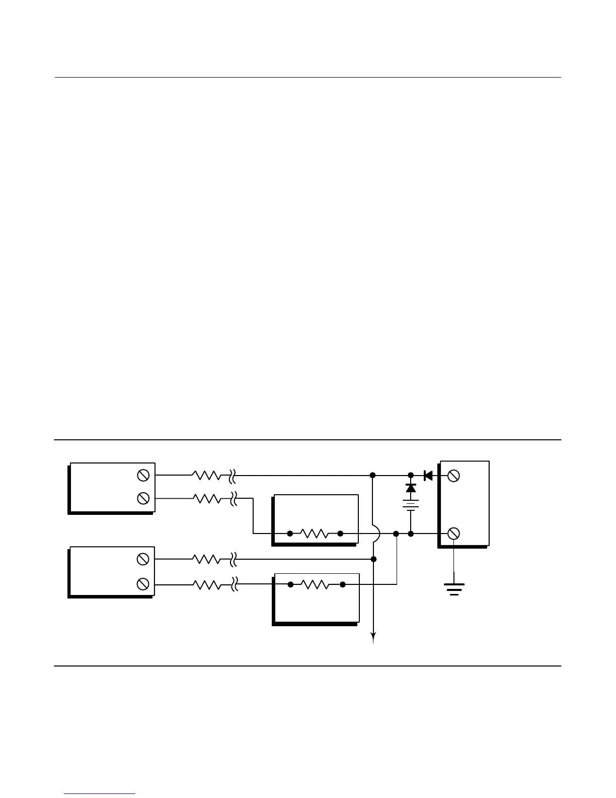
You can connect several instruments to a single master power supply as shown in figure 2‐12. In this case, the system
may be grounded only at the negative power supply terminal. In multichannel installations where several instruments
depend on one power supply, and the loss of all instruments would cause operational problems, consider an
uninterruptible power supply or a back‐up battery. The diodes shown in figure 2‐12 prevent unwanted charging or
discharging of the back‐up battery. If several loops are connected in parallel, make sure the net loop impedance does
not reach levels that would prevent communication.
Figure 2‐12. Multichannel Installations
R
Lead
R
Lead
R
Lead
+
+
-
-
To Additional
Instruments
Between
230 and 1100
if no Load Resistor
Instrument
No. 2
+
-
Instrument
No. 1
Readout
Device No. 2
Readout
Device No. 1
DC Power
Supply
+
-
E0364
Battery
Backup
+
-
R
Lead
Note that to provide a 4‐20 mA analog output signal, the DLC3010 must use HART polling address 0. Therefore, if a
multichannel installation is used with all transmitters in 4‐20 mA output mode, some means must be provided to
isolate an individual transmitter for configuration or diagnostic purposes. A multichannel installation is most useful if
the instruments are also in multi‐drop mode and all signaling is done by digital polling.
 Loading...


