Instruction Manual
D102748X012
Configuration
October 2014
46
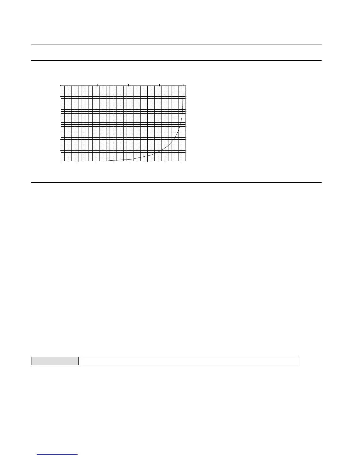
Figure 4‐5. Example Saturated Steam Curve Plotted from Values in Table 4‐3
0.0
0.05
0.10
0.15
0.20
0.25
0.30
0.35
0 100 200 300 400 500 600 700
SPECIFIC GRAVITY
TEMPERATURE _F
-18
100 200 300 375
TEMPERATURE _C
E0370
Process Temperature
The digital level controller can receive the process temperature from a resistance temperature detector (RTD)
connected to the unit or, if no RTD is connected to the unit, you can enter the process temperature directly. The digital
level controller uses the process temperature to make specific gravity corrections. Follow the prompts on the Field
Communicator to view or edit process temperature information.
D Proc Temp Source— Manual or RTD
Change Proc Temp Source— Select Keep Value, Edit Value, or Install RTD.
You must select the number of wires for an RTD; either 2 or 3.
For a 2‐wire RTD, you must specify the connecting wire resistance. If you know the resistance, select Resistance and
enter the resistance of the wire. 250 feet of 16 AWG wire has a resistance of 1 ohm. If you do not know the resistance,
select Wire Gauge/Length and the Field Communicator will prompt you for the length and gauge of the wire and
calculate the resistance.
D Proc Temp— Display the process temperature.
D RTD Wire Resistance— Displays the RTD wire resistance.
Device Information
Field Communicator Configure > Manual Setup > Device Information (2-2-4)
Follow the prompts on the Field Communicator display to view or edit information in the following fields.
D HART Tag— The HART tag is the easiest way to identify and distinguish between controllers in multi‐controller
environments. Use the HART tag to label controllers electronically according to the requirements of your
application. The tag you define is automatically displayed when a HART‐based communicator establishes contact
with the controller at power‐up. The tag may be up to eight characters long and has no impact on the primary
variable readings of the controller.
 Loading...


