Instruction Manual
D102748X012
Parts
October 2014
86
Parts List
Key Description Part Number
Note
Part numbers are shown for recommended spares only. For part
numbers not shown, contact your Emerson Process Management sales
office.
DLC3010 Digital Level Controllers
(figure 7‐1)
1 Transducer Module
(1)
2* Electronics Ass'y, includes alarm jumper (key 35) and
captive screws (key 36), header ass'y (key 38) and
encapsulated board
For use with transducer module 48B5739X012
(has obsolete Hall sensor on Flex circuit) 18B5529X022
For use with transducer module GE18497X022
(has new Hall sensor on rigid boards) 18B5529X032
Key Description Part Number
3 Cover Assy, includes O‐ring (key 21)
4 LCD Meter Ass'y, includes alarm jumper (key 35),
header ass'y (key 38) and captive screws (key 40),
and LCD Meter ass'y 28B5738X012
5* Terminal Box Ass'y 28B5740X022
6 Terminal Box Cover Ass'y, includes labels
(key 30 and 64) and set screw (key 31)
7 Screw, hex socket
(2)
8 Nameplate
9 Drive Screw, 18‐8 SST
21* O‐ring, nitrile
(3)
1K1810X0012
32 Adaptor Ring, A03600
33 Stud, SST (4 req'd)
34 Hex Nut, 304 SST (4 req'd)
35 Alarm Jumper
(2)(4)(5)
36 Screw, captive, 18‐8 SST
For electronics ass'y (2 req'd)
(4)
38 Header Assembly, dual row (not shown)
(2)(4)(5)
40 Screw, captive, 18‐8 SST
For LCD meter (2 req'd)
(5)
18B5732X012
66 Anti‐Seize Sealant (not furnished with instrument)
67 Thread locking adhesive (medium strength)
(not furnished with instrument)
70 Lithium grease (not furnished with instrument)
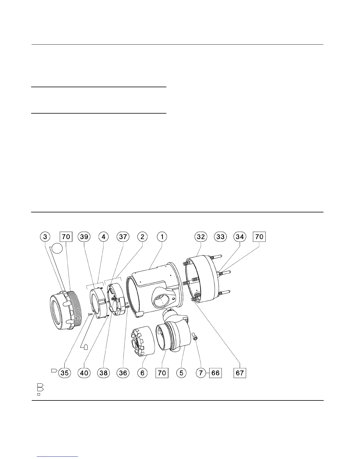
Figure 7‐1. DLC3010 Digital Level Controller Assembly
NOTES:
1 INSTALL ALARM JUMPER (KEY 35) ON ELECTRONICS ASSEMBLY (KEY2) WHEN LCD METER (KEY 4) IS NOT INSTALLED.
2 LOCATION OF ALARM JUMPER (KEY 35) WHEN LCD METER (KEY 4) IS INSTALLED.
1
2
58B5510‐D
APPLY LUB/THREADLOCK
21
*Recommended spare parts
1. These parts are not replaced in the field due to serialization and characterization
issues, but can be replaced at a qualified service center. Contact your Emerson
Process Management sales office for additional information.
2. Included in small hardware spare parts kit.
3. Included in spare O‐rings kit.
4. Included in the Electronics Ass'y, key 2
5. Included in the LCD Meter Ass'y. key 4
 Loading...


