Instruction Manual
D102748X012
Parts
October 2014
87
Key Description Part Number
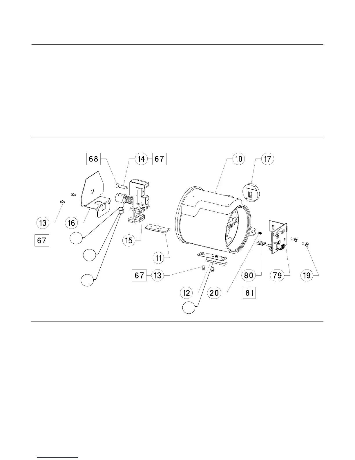
Transducer Assembly (figure 7‐2)
11 Inner Guide, aluminum
12 Handle Ass'y aluminum/SST
13 Screw, hex socket, 18‐8 SST (4 req'd)
14 Screw, cap, 18‐8 SST
15* Lever Assembly, aluminum/SST/NdFeB/CS 38B5509X042
16 Coupling Shield, 18‐8 SST
17 Ring, align/clamp
Key Description
19 Machine Screw, pan head
20 Set Screw, 18‐8 SST
(2)
31 Set Screw, hex socket, 18‐8 SST
(2)
67 Thread Locking adhesive (medium strength)
(not furnished with instrument)
68 Sealant
76 Clamp Nut, 18‐8 SST
(2)(6)
77 Spring Lock Washer, 18‐8 SST
(2)(6)
79 Transducer Board Assembly
(1)
80 Hall Guard
81 Compound, silicone
82 Bolt, lock, coupling block, SST
(6)
Figure 7‐2. DLC3010 Digital Level Controller Transducer Assembly
GE18497
31
77
76
82
*Recommended spare parts
1. These parts are not replaced in the field due to serialization and characterization
issues, but can be replaced at a qualified service center. Contact your Emerson
Process Management sales office for additional information.
2. Included in small hardware spare parts kit.
6. Included in Coupling Hardware Spare Parts Kit
 Loading...


