Instruction Manual
D102748X012
Maintenance & Troubleshooting
October 2014
81
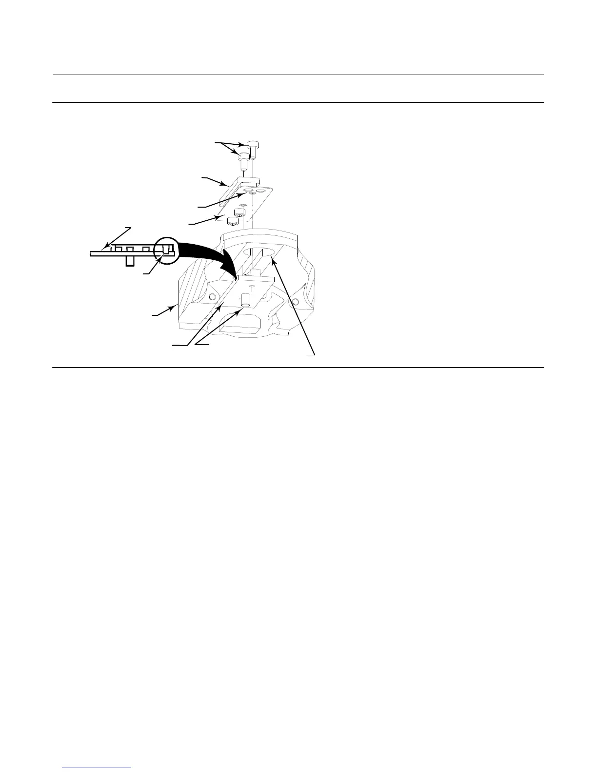
Figure 6‐3. Installing Inner Guide and Access Handle Assembly
ZERO LOCKING PIN
INNER GUIDE
(KEY 11)
VENT HOLE
LUBRICATE
THIS SURFACE
VENT HOLES
HANDLE
ASSEMBLY
(KEY 12)
SCREWS (KEY 13)
LUBRICATE
THIS SURFACE
TRANSDUCER
HOUSING
ACCESS HOLE
E0381
6. Place the inner guide in the slot inside the transducer housing so that the vent holes in the inner guide (the milled
slots in the inner guide, see figure 6‐3) face the exterior of the housing and are over the access hole.
7. Apply a thin coat of a light grade of grease to the surface of the replacement handle assembly (see figure 6‐3) where
it will contact the transducer housing.
8. Install the handle assembly (key 12) in the slot of the transducer housing over the inner guide (key 11) so that the
vent holes in the handle assembly are over the access hole.
9. Install two screws (key 13) to secure the handle assembly (key 12) to the inner guide (key 11). Tighten the screws to
0.48 NSm (4.2 lbfSin).
10. Press down on the handle as shown in figure 2‐4 and slide it forward to make sure it works smoothly and that the
zero locking pin engages the lever assembly. Also check for free travel of the lever assembly when the handle is in
the unlocked position.
11. Install the coupling shield (key 16) and secure with the two screws (key 13). Tighten the screws to 0.48 NSm
(4.2 lbfSin).
12. Refer to figure 7‐1. Install the adapter ring
(key 32) on the studs (key 33) and secure with hex nuts (key 34).
13. When re‐installing the digital level controller, follow the appropriate procedure outlined in the Installation section.
Also setup the digital level controller as described in the Setup and Calibration section.
Lever Assembly
Removing the Lever Assembly
The lever assembly is located in the transducer housing. Unless indicated otherwise, refer to figure 7‐2.
 Loading...


