Instruction Manual
D102748X012
Principle of Operation
October 2014
94
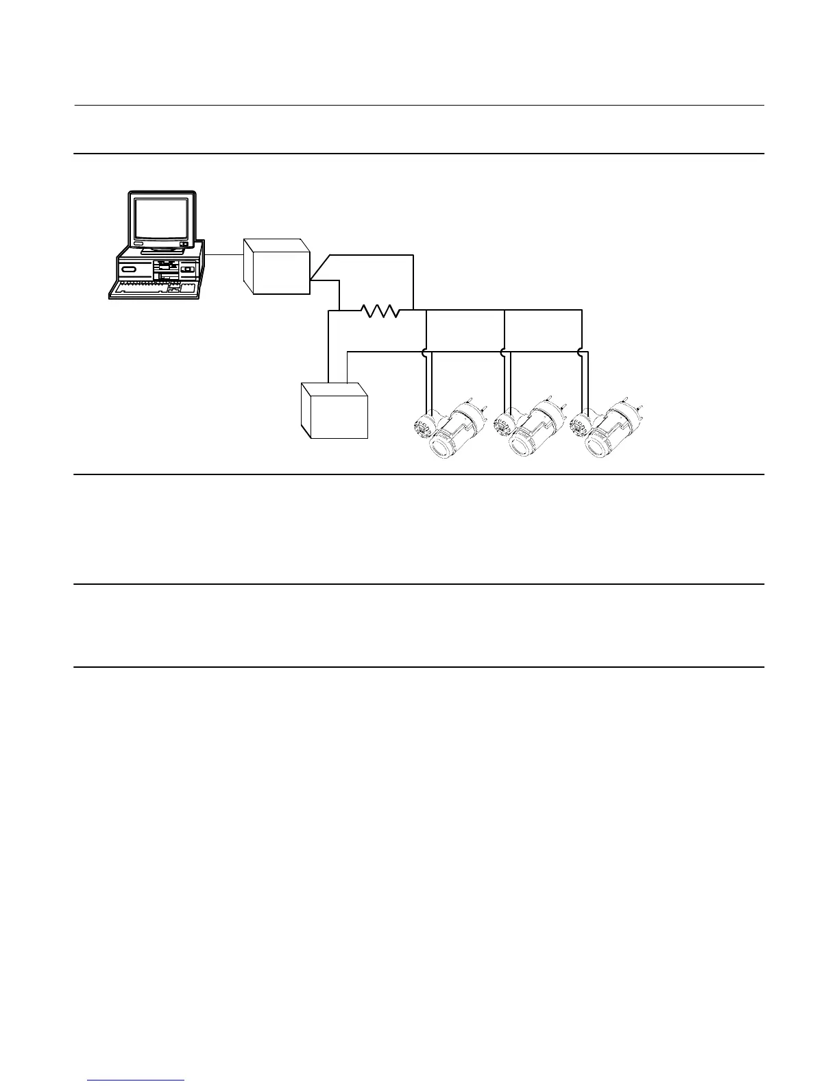
Figure A‐2. Typical Multidropped Network
E0375
HOST
BELL 202
MODEM
POWER
SUPPLY
LOAD
The Field Communicator can test, configure, and format a multidropped DLC3010 digital level controller in the same
way as in a standard point‐to‐point installation.
Note
DLC3010 digital level controllers are set to address 0 at the factory, allowing them to operate in the standard point‐to‐point
manner with a 4-20 mA output signal. To activate multidrop communication, the address must be changed to a number between
1 and 15. This change deactivates the 4-20 mA analog output, sending it to 4 mA. The failure mode current also is disabled.
Digital Level Controller Operation
The DLC3010 digital level controller is a loop‐powered instrument that measure changes in liquid level, level of an
interface between two liquids, or density of a liquid. Changes in the buoyancy of a displacer suspended in a vessel vary
the load on a torque tube. The displacer and torque tube assembly constitute the primary mechanical sensor. The
angular deflection of the torque tube is measured by the instrument transducer, which consists of a magnet system
moving over a Hall effect device. A liquid crystal display (LCD) meter can display the analog output; process variable
(level, interface level, or density); the process temperature, if an RTD (resistance temperature detector) is installed;
the degrees of torque tube rotation; and percent range.
The instrument uses a microcontroller and associated electronic circuitry to measure the process variable, provide a
current output, drive the LCD meter, and provide HART communications capability. Figure A‐3 shows the digital level
controller assembly. Figure A‐4 is a block diagram of the main components in the instrument electronics; the LCD
meter, the processor module, the transducer board, and the terminal board. The processor module contains the
microprocessor, the analog‐to‐digital (A/D) converters, loop interface, signal conditioning, the digital‐to‐analog (D/A)
output, power supply and interfaces to other boards.
 Loading...


