Instruction Manual
D200138X012
3582, 582i, and 3583
February 2015
53
For Mounting 3582, 3582i, and 3583 on
657 or 667 Actuator with Side‐Mounted
Handwheel
Key Description
Note
Part numbers are shown for recommended spares only. For part
numbers not shown, contact your Emerson Process Management sales
office.
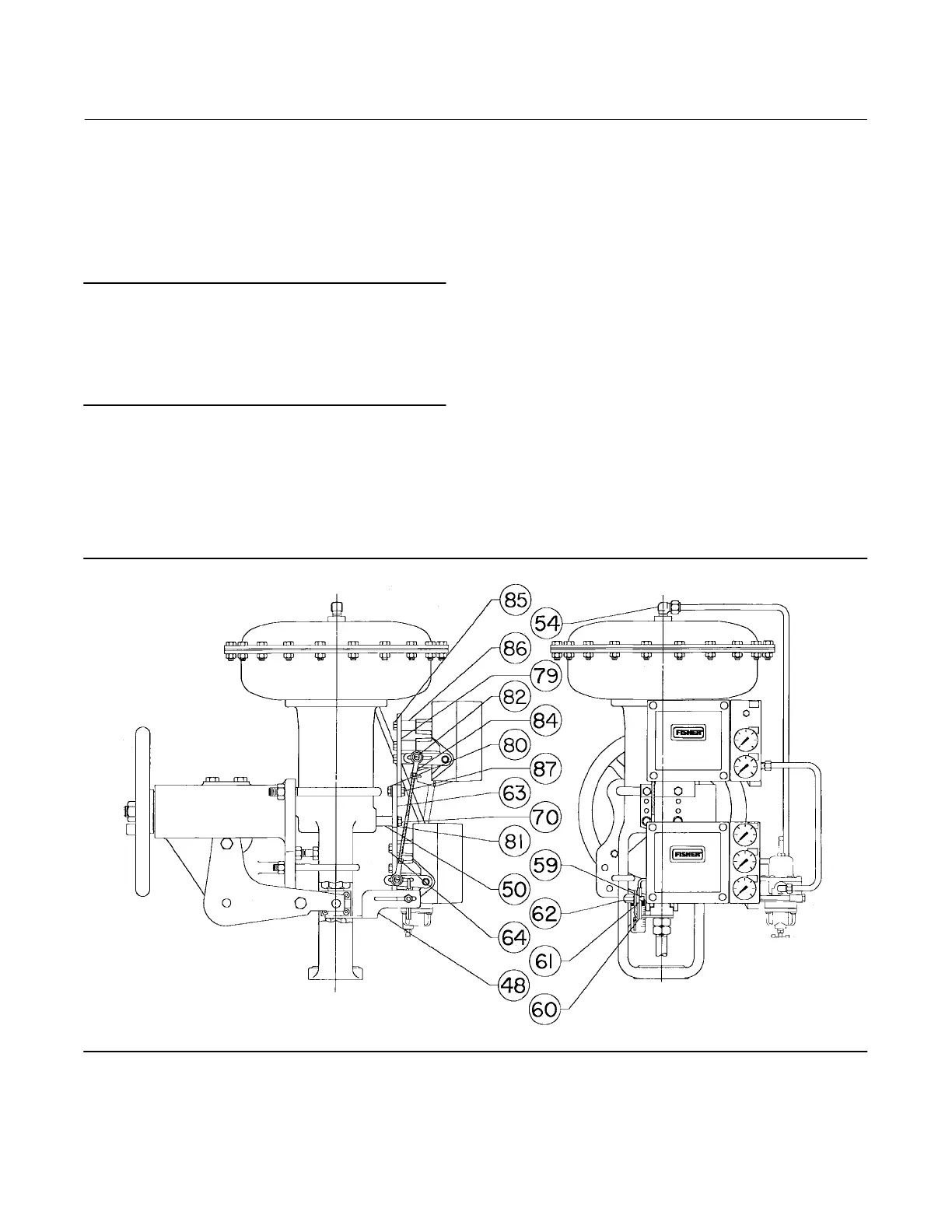
The following parts (key numbers 48 through 87) are used when
mounting both a 3582 positioner and a 3583 transmitter on a 657 or
667 Size 45 actuator with side‐mounted handwheel.
48 Connector Arm, pl steel
50 Spacer, steel (2 req'd)
54 Elbow, 3/8‐inch, brass
55 Connector, 3/8‐inch brass (not shown)
59 Pin Lock, SST (2 req'd)
Key Description Part Number
60 Travel Pin, SST (2 req'd) 10A2167X012
61 Pin Holder, SST (2 req'd)
62 Cap Nut, SST (2 req'd)
63 Mounting Plate, steel (2 req'd)
For integrally mounted 67CFR
For separately mounted 67CFR
64 Cap Screw, pl steel (8 req'd)
70 Cap Screw, pl steel (2 req'd)
79 Mounting Plate, steel
80 Hex Nut, pl steel, for 667 only (2 req'd)
81 Lockwasher, pl steel
657 (2 req'd)
667 (4 req'd)
82 Machine Screw, pl steel (2 req'd)
83 Elastic Stop Nut, pl steel (not shown) (2 req'd)
84 Connecting Linkage, pl steel
85 Cap Screw, pl steel, for 667 only (5 req'd)
86 Spacer, pl steel for 667 only (5 req'd)
87 Cap Screw, pl steel for 667 only (2 req'd)
Figure 27. Typical Application of Transmitter and Positioner
41B8568‐C