EasyManua.ls Logo

Fisher 64 User Manual

Fisher 64
4 pages
To Next Page IconTo Next Page
Page #1 background imageLoading...
Page #1 background image
64 and 67C Series Regulators
D450128T012
Instruction Manual
Form MCK-2133
December 2008
www.emersonprocess.com/regulators/lp
!
WARNING
Failure to follow these instructions or to properly
install and maintain this equipment could result in
an explosion and/or re causing property damage
and personal injury or death.
Fisher
®
equipment must be installed, operated,
and maintained in accordance with federal, state,
and local codes and Fisher instructions. The
installation in most sates must also comply with
NFPA No. 54 and 58 standards.
Only personnel trained in the proper procedures,
codes, standards, and regulations of the
LP-Gas industry should install and service
this equipment.
THINGS TO TELL THE GAS CUSTOMER:
1. Point out the regulator’s vent to the customer (or vent
assembly or vent tube), and stress that this opening must
remain unobstructed at all times. Tell the customer to be
sure to check the vent opening after a freezing rain, sleet
storm, or snow to makes sure ice has not formed in the vent.
2. Show the customer to shutoff valve on the container. The
customer should close this valve immediately if gas is
smelled, appliance pilot lights fail to stay on or appear higher
than usual, or any other abnormal situation occurs.
3. Tell the customer to call your company to service the
regulator if the regulator vents gas or a leak develops in the
system. Only a qualied gas service person should
install or service the regulator.
Introduction
Scope of Manual
This manual provides instructions and maintenance for the
following high pressure regulators: Types 64, 64KB, 64SR,
67CW, 67CH, 67CD, and 67CN regulators.
Description
The 64 and 67C Series direct-operated regulators (Figure 1) are
designed for high-pressure (pounds per square inch) service and can
be used on either vapor applications in LP-Gas, Natural Gas and Air
or liquid LP-Gas applications. Depending upon type, outlet pressure
ranges from 3 to 135 psig (0,21 to 9,3 bar). The Type 64SR can be
used as a First Stage LP-Gas regulator–reducing tank pressure to
10 psig (0,69 bar) for a Second Stage regulator. The Type 64KB
is the only regulator in this series suitable for anhydrous ammonia
(NH
3
) service. The regulators are normally painted red.
64 and 67C Series Regulators Instruction Manual
67C SERIES REGULATORS
W8810
64 SERIES REGULATOR
Figure 1. 64 and 67C Series Regulators
P1027
Table 1. Available Congurations
CAUTION
Do not use the 67C, 64, or 64SR Series regulators
in anhydrous ammonia (NH
3
) service. They
contain brass materials that are not compatible
with anhydrous ammonia (NH
3
).
TYPE DESCRIPTION
64
Basic regulator with four spring ranges from 3 to 100 psig
(0,21 to 6,9 bar).
64SR
Internal relief version with three spring ranges from 3 to 35 psig
(0,21 to 2,4 bar).
64KB
For use with anhydrous ammonia (NH
3
) with handwheel
adjustment and ve spring ranges from 3 to 100 psig
(0,21 to 6,9 bar). Includes a special diaphragm protector.
67CW
Basic regulator with wrench adjustment and 4 spring ranges from
3 to 135 psig (0,21 to 9,3 bar); no relief.
67CH Basic regulator with handwheel adjustment.
67CD Basic regulator with dial cap adjustment.
67CN Basic regulator, factor set with not eld adjustment.
OBSOLETE DOCUMENT
Question and Answer IconNeed help?

Do you have a question about the Fisher 64 and is the answer not in the manual?

Fisher 64 Specifications

General IconGeneral
TypePneumatic Controller
ActionDirect or Reverse
Ambient Temperature Range-40 to 180°F (-40 to 82°C)
Output Signal3 to 15 psig (0.2 to 1.0 bar)
Accuracy±1% of span
Repeatability±0.5% of span
Hysteresis±0.5% of span
MountingPipe
MaterialsAluminum, Stainless Steel, and other corrosion-resistant materials
Supply Pressure20 psi

Summary

Introduction

Scope of Manual

Outlines the manual's coverage of specific regulator models and their applications.

Product Information

Customer Information

Key details for gas customers regarding regulator vents and shutoff valve operation.

Regulator Description

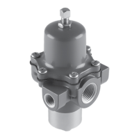
Details the design and applications of 64 and 67C series regulators for high-pressure service.

Anhydrous Ammonia Warning

Caution against using specific regulators with anhydrous ammonia due to material incompatibility.

Specifications

General Specifications

Covers body size, pressure ratings, flow coefficients, and temperature capabilities for regulators.

Outlet Pressure Ranges

Lists available outlet pressure ranges for different regulator types and spring settings.

Installation

Installation Warnings

Emphasizes safety precautions and the need for qualified personnel during regulator installation.

Installation Procedures

Step-by-step guidance for installing regulators, including vent protection and location.

Liquid Service Installation

Details requirements for regulators in liquid service, including shutoff valves and vent lines.

Overpressure Protection

Protection Requirements

Explains the need for overpressure protection and the function of internal/external relief valves.

Startup and Adjustment

Startup Procedure

Guides on slowly opening valves and monitoring pressure during initial startup.

Pressure Adjustment

Details how to adjust outlet pressure using the control spring or handwheel.

Operation and Maintenance

Shutdown Procedure

Describes the correct sequence for shutting down the regulator and releasing pressure.

Maintenance Warnings

Highlights safety precautions and warnings before performing any maintenance or disassembly.

Regular Inspection

Details periodic inspection points to identify potential issues like corrosion or vent blockage.

Regulator Repair

Guidelines for repairing regulators, emphasizing the use of genuine parts and testing.

Related product manuals