Do you have a question about the Fisher 67CF and is the answer not in the manual?
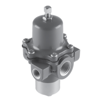
Provides an overview of the 67C Series instrument supply regulators.
Details the typical uses and applications of 67C Series direct-operated regulators.
Lists general ratings and specifications for 67C Series regulators.
Explains the internal relief valve function in specific 67C Series regulator types.
Details the Smart Bleed™™ option for exhausting downstream pressure upon inlet pressure loss.
Discusses the need for external protection when inlet pressure exceeds regulator ratings.
Instruction for regulators shipped mounted on other units.
Highlights potential hazards like injury, damage, or explosion from gas release.
Covers guidelines for proper regulator installation, inspection, and handling.
Steps for slowly opening valves and monitoring pressure during startup.
Method for adjusting outlet pressure using screw or handwheel.
Steps for safely shutting down the regulator by closing block and opening vent valves.
Emphasizes regular inspection and replacement of regulator parts based on service conditions.
Detailed steps for maintaining the trim components of 67C, 67CR, 67CS, and 67CSR regulators.
Procedures for removing, inspecting, and reinstalling the diaphragm assembly.
Steps for maintaining filter elements and trim for 67CF, 67CFR, 67CFS, and 67CFSR models.
Guidance on how to order parts, including required information.
Comprehensive list of parts with descriptions and part numbers for 67C Series regulators.
Details kits for converting to automatic drain functionality.
Lists different body materials and drain valve types with corresponding part numbers.
Details flange screws and O-rings with their part numbers and material types.
Provides part numbers and specifications for dripwells and filter elements.
Lists part numbers for spring cases, valve cartridges, and valve plugs.
Details part numbers for valve springs and retainers.
Lists part numbers for soft seats and diaphragm assemblies.
Details diaphragm assemblies for different regulator types and their part numbers.
Lists springs for various regulator types and pressure ranges with part numbers.
Details part numbers for adjusting screws and panel mounting hardware.
Illustrates the assembly of Type 67CFS or 67CFSR regulators with keyed components.
Shows the diagram for the optional panel mount configuration.
Diagrams illustrating vent positions on the spring case for 67C Series regulators.
Diagrams showing drain valve positions for 67CF, 67CFR, 67CFS, and 67CFSR regulators.
Close-up view of the diaphragm assembly (Key 16) with component labels.
Illustration and availability of the optional closing cap for spring case vents.
Detailed diagram of the valve cartridge assembly (Key 10) with dimensions.
Diagram showing spacer dimensions and its assembly for installation.
Detailed list of parts identified by key numbers and their corresponding part numbers.
Lists parts for mounting the 67C Series regulator onto a 2500 Series Controller.
Provides contact details for Emerson Process Management in different regions.
| Action | Direct or Reverse |
|---|---|
| Housing Material | Aluminum |
| Type | Pneumatic |
| Accuracy | ±1% of output pressure range |
| Mounting | Pipe |