Do you have a question about the Fisher 685 and is the answer not in the manual?
Provides information on installation, maintenance, and parts ordering for Fisher 685 piston actuators.
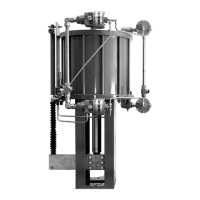
Details the Fisher 685 as a double acting piston actuator providing accurate, high thrust output for various applications.
Specifies minimum and maximum allowable operating pressures for the actuator.
Outlines the available travel range for the Fisher 685 piston actuator.
Refers to a table detailing the thrust capabilities of the actuator.
Lists available piston diameters and areas in specified increments.
Defines the standard, low, and high operative temperature limits for the actuator.
Specifies compatible yoke boss and valve stem diameters for actuator mounting.
Lists standard and optional pressure connection types for the actuator.
Notes availability of mounting kits for positioner integration.
Details the construction materials used for various parts of the actuator.
Refers to tables providing approximate weights of the actuator constructions.
Refers to a table specifying the load ratings for lifting points.
Lists optional certifications such as PED and ATEX compliance.
Provides contact information for Emerson Automation Solutions Educational Services for training courses.
Explains how the actuator uses pneumatically controlled piston movement to generate thrust.
Describes the function and capabilities of the optional handwheel manual override.
Presents standard actuator constructions with details on size, dimensions, and travel.
Provides thrust output data in Newtons and pounds-force at various supply pressures.
Lists approximate weights for actuator constructions that do not include handwheels.
Lists approximate weights for actuator constructions that include handwheels.
Specifies load ratings for actuator lifting points based on size and orientation.
Provides essential safety warnings regarding protective gear and pressure limits during installation.
Details procedures for mounting the actuator, emphasizing safe handling and proper support.
Highlights cautionary notes for horizontal orientation and handling of actuator assemblies.
Warns about potential stem fracture risk in three-way valve applications with rapid stroking.
Provides a step-by-step procedure for mounting the actuator onto a push-down-to-close valve.
Advises caution to prevent damage to valve stem and seating surfaces during mounting.
Explains the necessity of opening the bypass valve before using the handwheel for manual operation.
Details the steps for engaging the manual handwheel override with the stem connector.
Provides specific instructions for handwheel operation based on valve type (push-down-to-close/open).
Describes the procedure for disengaging the manual handwheel.
Lists specifications for handwheel operation, including output thrust and force requirements.
Outlines critical safety precautions to prevent injury from pressure release and during maintenance.
Provides an overview of maintenance procedures, including disassembly and seal replacement.
Details the step-by-step procedure for removing the actuator from a valve.
Provides steps for replacing internal piston seals, bearing seals, and O-rings.
Details the procedure for replacing the O-ring in the lower head.
Outlines replacing the wear ring and quad seal on the piston.
Details replacing the piston rod O-ring and the quad seal on the piston.
Covers installing the cylinder onto the upper head and replacing the upper head O-ring.
Table 8 provides torque specifications for tie bolts based on diameter.
Provides guidance on how to order parts, referencing serial numbers and sales offices.
Warns against using non-genuine parts, which may void warranty or cause damage.
Lists available parts kits containing seals and O-rings for standard temperature constructions.
Lists common parts with key numbers, descriptions, and references to parts kits.
Lists parts specifically related to the manual handwheel assembly with key numbers.
| Brand | Fisher |
|---|---|
| Model | 685 |
| Category | Controller |
| Language | English |