Instruction Manual
D103626X012
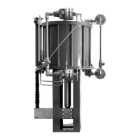
685 Piston Actuator
June 2017
10
piston rod Oring (key 19), heat the piston assembly using a torch and unthread the piston rod (key 17) from the
piston (key 5).
15. After the piston rod (key 17) has completely cooled, remove the piston rod Oring (key 19). Clean the piston rod
Oring groove with a light degreaser. Lightly grease a new piston rod Oring and install onto the piston rod.
16. Reinstall piston rod (key 17) onto piston (key 5) using thread locking compound.
17. Clean piston seal grooves. Install new lightly greased quad seal (key 7) onto piston (key 5).
18. Without grease, trim to length and then install a new wear ring (key 6).
19. Lift cylinder (key 4) vertically and place on a flat surface. Take extra precaution to avoid scratching or gouging the
inner diameter of the cylinder.
20. Remove Oring (key 2) from the upper head (key 1) and clean the seal groove. Install lightly greased new Oring
into upper head seal groove.
21. Install cylinder (key 4) onto upper head (key 1) making sure the Oring (key 2) does not move out of its groove.
22. Carefully install the piston assembly (keys 5, 6, 7, 17, and 19) into cylinder (key 4) making sure all seals and Orings
stay in place on the outside diameter of the piston (key 5).
23. Install tie bolts (key 3) into upper head (key 1).
24. Carefully install the yoke (key 21) and the lower head (key 9) assembly onto cylinder (key 4) taking care not to
damage threads on the tie bolts (key 3). Be sure the Oring (key 2) is in place during this step.
25. Install lock washers (key 10) and tie rod hex nuts (key 11) onto tie bolts (key 4). Torque in a crisscross pattern
according to table 2.
26. Refer to the Actuator Mounting section of this manual for instructions on mounting and installing the actuator
onto a valve.
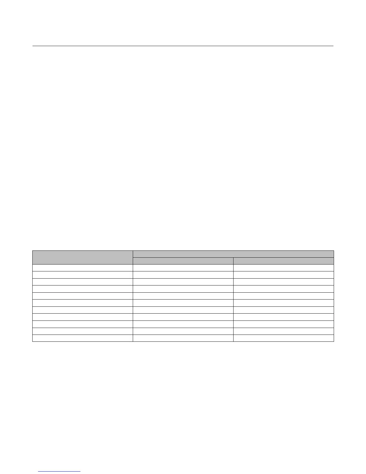
Table 8. Tie Bolt Torque
BOLT DIAMETER
TORQUE
N•m lbf•ft
1/4-20 8 6
5/16-18 15 11
3/8-16 26 19
7/16-14 39 29
1/2-13 60 44
9/16-12 84 62
5/8-11 115 85
3/4-10 198 146
7/8-9 313 231
1-8 445 328
1-1/8-7 662 488