EasyManua.ls Logo

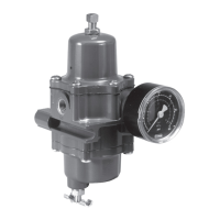
Fisher 67CF - Diagrams and Component Identification; Type 67 CFS or 67 CFSR Assembly Diagram; Optional Panel Mount Diagram; Spring Case Vent Positions

Fisher 67CF
12 pages
To Next Page IconTo Next Page
To Previous Page IconTo Previous Page
Loading...
67C Series
10
18
33
L
L
L
L
16
1
5
6
9
2
10
19
18
17
15
11
14
12
13
7
45
20 31
26
37
4
Figure 7. 67C Series Optional Panel Mount
Figure 6. Type 67CFS or 67CFSR Assembly
40C1728
40C1728
Figure 8. 67C Series Spring Case Vent Positions
3








B2699_C
3
250 PSI
MAX INLET












B2699_D
Figure 9. Types 67CF, 67CFR, 67CFS, and 67CFSR
Drain Valve Positions
18
33
16
1
5
6
9
2
10
19
18
17
15
11
14
12
13
7
45
20 31
26
37
4


Related product manuals