• O-ring (key 14)
• O-ring (key 70)
• Diaphragm (key 9)
• O-ring (key10)
• Bottom Plug (key 11)
• Flanged Locknut (key 13)
9. Reassemble in the reverse order. Tighten ange
locknut (key 13) to proper torque (see Table 13).
Travel Indicator Assembly Maintenance
Travel indicator assembly key numbers are referenced
in Figures 10, 14 and 18. The indicator assembly
can be removed and installed without removing the
bonnet (key 2) from the body (key 1). Travel indicator
maintenance is performed for two reasons:
a. When damaged or worn parts need replacing.
b. When travel indicator is removed and replaced
with a travel indicator plug assembly.
!
WARNING
Avoid personal injury or damage
to property from sudden release
of pressure or uncontrolled gas or
other process uid. Before starting
to disassemble, carefully release all
pressures according to the shutdown
procedure. Use gauges to monitor inlet,
loading and outlet pressures while
releasing these pressures.
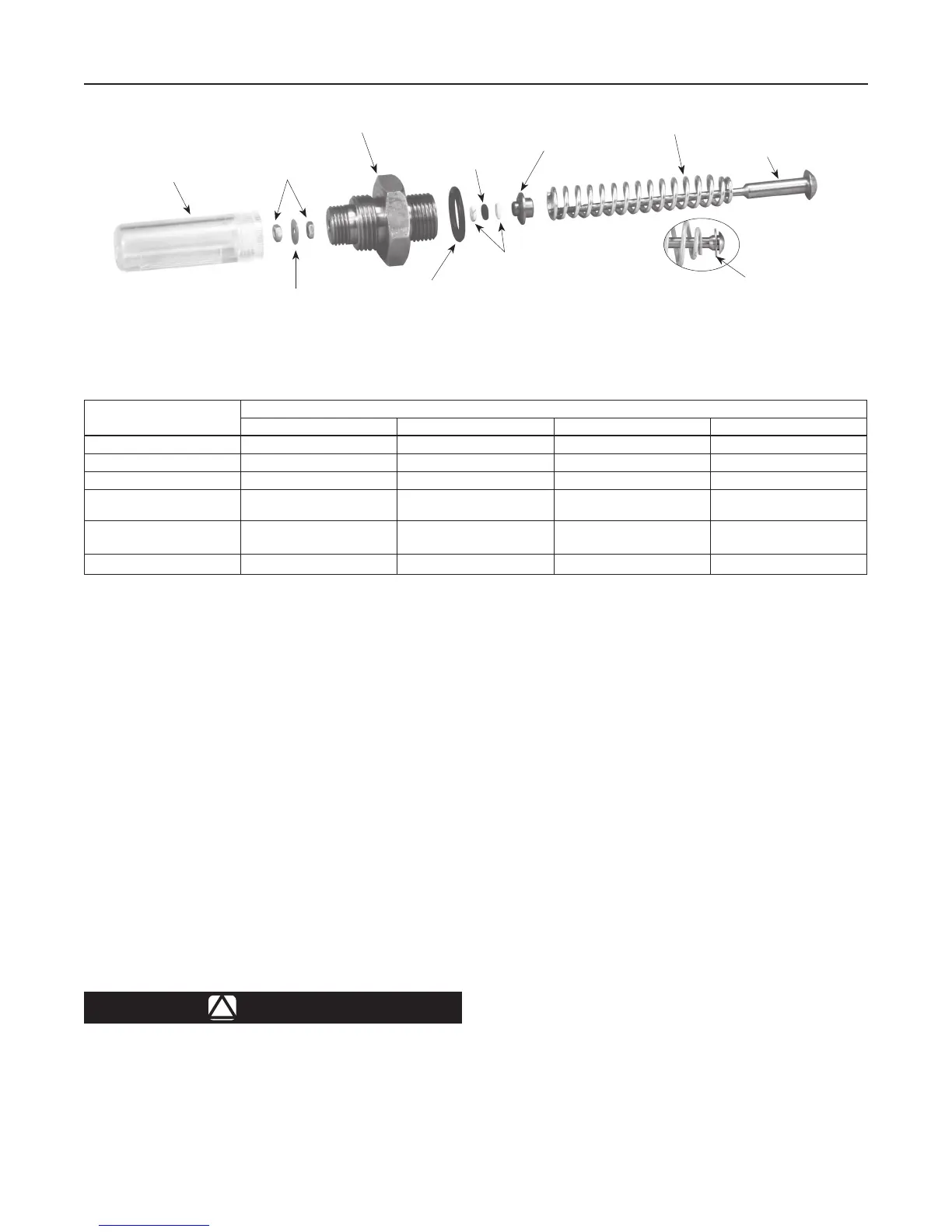
1. Remove the indicator protector (key 22, Figure 14)
and indicator cover (key 21).
2. Remove the rst hex nut (key 4) and the indicator
washer (key 20).
3. Unscrew the second hex nut (key 4) on the top of
the indicator stem (key 15). Do not remove.
4. Use a wrench to remove indicator tting (key 19).
5. Lift out travel indicator assembly. If replacing travel
indicator with travel indicator plug, skip to step 9.
6. Compress the main spring (key 12). Remove the
second hex nut (key 4). Parts will separate easily
when the hex nut is removed.
7. Slide the indicator stem (key 15) out of the
indicator tting (key 19). The main spring (key 12)
and upper spring seat (key 17) will be free.
8. If necessary, use the indicator stem (key 15) to pry
the back-up rings (key 16) and O-ring (key 18) out
of the indicator tting (key 19).
BODY SIZE, NPS / DN
TORQUE, FT-LBS / N•m
Cap Screw Flange Locknut Indicator Fitting Indicator Plug
1 or 1-1/4 x 1 / 25 or 32 x 25 75 to 95 / 102 to 129 4 to 6 / 5.4 to 8.1 90 to 160 / 122 to 217 90 to 160 / 122 to 217
2 x 1 or 2 / 50 x 25 or 50 55 to 70 / 75 to 95 6 to 8 / 8.1 to 11 90 to 160 / 122 to 217 90 to 160 / 122 to 217
3 / 80 100 to 130 / 136 to 176 19 to 25 / 26 to 34 200 to 300 / 271 to 407 200 to 300 / 271 to 407
4, 6 x 4 or 8 x 4 /
100, 150 x 100 or 200 x 100
160 to 210 / 217 to 285 19 to 25 / 26 to 34 200 to 300 / 271 to 407 200 to 300 / 271 to 407
6, 8 x 6 or 12 x 6 /
150, 200 x 150 or 300 x 150
275 to 300 / 373 to 407 50 to 100 / 68 to 136 300 to 425 / 407 to 577 300 to 425 / 407 to 577
8 / 200 400 to 450 / 542 to 610 90 to 110 / 122 to 149 300 to 425 / 407 to 577 300 to 425 / 407 to 577
Table 13. Torque Values
Figure 10. Travel Indicator Parts
INDICATOR COVER
(KEY 21)
HEX NUTS
(KEY 4)
INDICATOR FITTING
(KEY 19)
O-RING
(KEY 18)
UPPER SPRING
SEAT (KEY 17)
MAIN SPRING
(KEY 12)
INDICATOR STEM
(KEY 15)
WASHER (KEY 79)
(NPS 6 / DN 150 SIZE ONLY)
BACK-UP
RINGS
(KEY 16)
INDICATOR
O-RING (KEY 6)
INDICATOR
WASHER (KEY 20)
19
Type EZR

 Loading...


