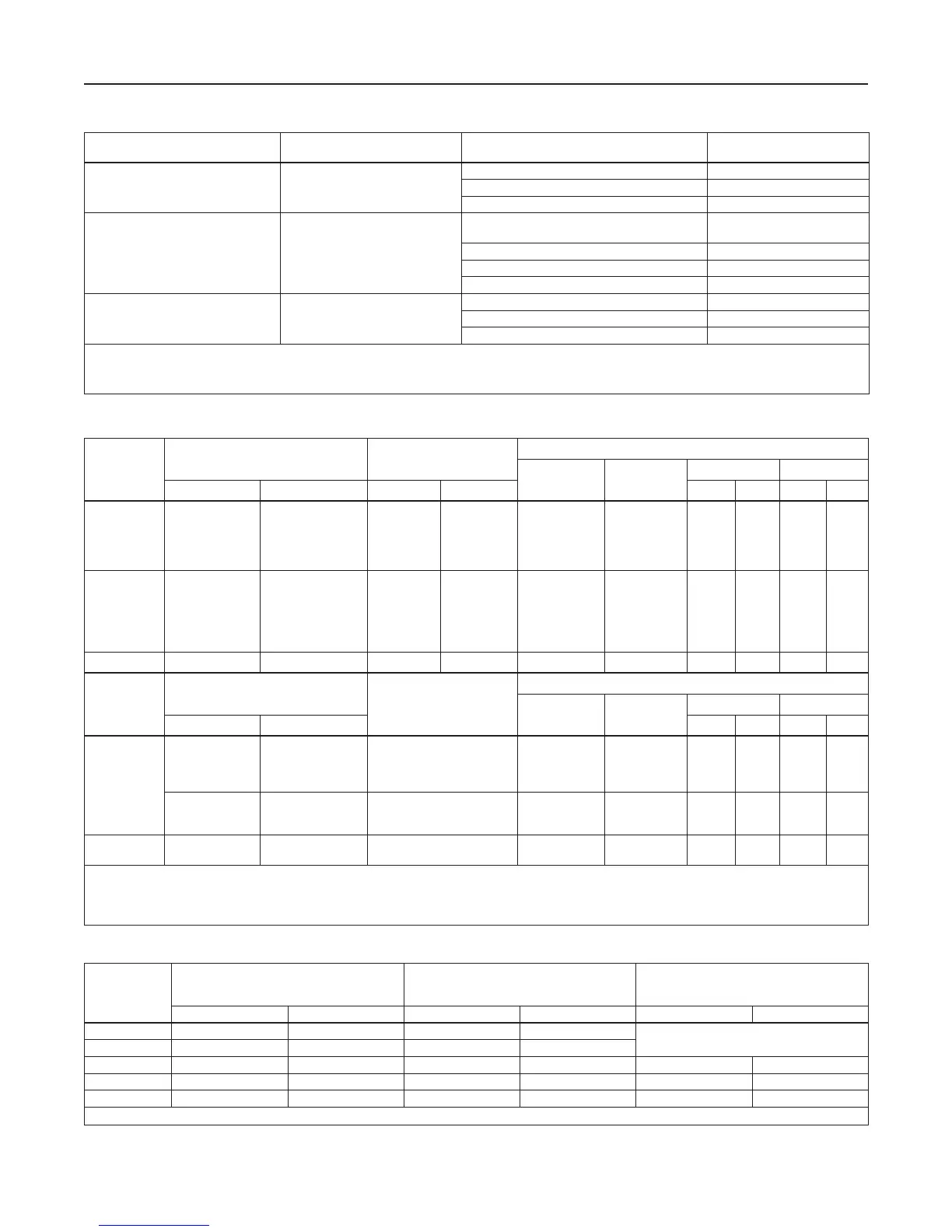
MAIN VALVE BODY SIZE, NPS / DN MAIN VALVE BODY MATERIAL END CONNECTION STYLE
(1)
STRUCTURAL DESIGN
RATING
(2)
2 x 1, 2, 3, 4 and 6 /
50 x 25, 50, 80, 100 and 150
Cast iron
NPT (NPS 2 x 1 and 2 / DN 50 x 25 and 50 only) 400 psig / 27.6 bar
CL125 FF 200 psig / 13.8 bar
CL250 RF 500 psig / 34.5 bar
1, 1-1/4 x 1
(3)
, 2 x 1, 2, 3, 4,
6 x 4
(4)
, 8 x 4
(4)
, 6, 8 x 6
(4)
and 12 x 6
(4)
/
25, 32 x 25, 50 x 25, 50, 80,
100,150 x 100, 200 x 100, 150,
200 x 150 and 300 x 150
WCC Steel
NPT or SWE (NPS 1, 2 x 1 and 2 /
DN 25, 50 x 25 and 50 only)
1500 psig / 103 bar
CL150 RF 290 psig / 20.0 bar
CL300 RF 750 psig / 51.7 bar
CL600 RF or BWE 1500 psig / 103 bar
8 / 200 LCC Steel
CL150 RF 290 psig / 20.0 bar
CL300 RF 750 psig / 51.7 bar
CL600 RF 1500 psig / 103 bar
1. Ratings and end connections for other than ASME standard can usually be provided. Contact your local Sales Ofce for assistance.
2. See Tables 3, 8, 10 and 11 for diaphragm materials and additional pressure ratings.
3. Available in steel NPT only.
4. NPS 6 x 4, 8 x 4, 8 x 6, 12 x 6 / DN 150 x 100, 200 x 100, 200 x 150, 300 x 150 Types EZR and 399 bodies are not the same as the EW valve bodies and are not interchangeable.
Table 1. Main Valve Body Sizes, End Connection Styles and Body Ratings
TYPE
MAXIMUM INLET PRESSURE
MAXIMUM EMERGENCY OUTLET
PRESSURE OR MAXIMUM EMERGENCY
SENSE PRESSURE
(1)
MAXIMUM BLEED (EXHAUST) PRESSURE
FOR MONITOR PILOTS
psig bar psig bar psig bar
161AY 150 10.3 150 10.3
- - - -
161EB 1500 103 1200 82.7
161AYM 150 10.3 150 10.3 150 10.3
161EBM 1500 103 1200 82.7 1500 103
PRX Series 1480 102 1480 102 1480 102
1. Maximum pressure to prevent the casings from bursting during abnormal operation (leaking to atmosphere and internal parts damage may occur).
Table 3. Pilot Pressure Ratings
Table 2. Outlet (Control) Pressure Ranges, Proportional Bands and Pilot Control Spring Information
TYPE
OUTLET (CONTROL)
PRESSURE RANGE
PROPORTIONAL BAND
(1)(3)
PILOT CONTROL SPRING INFORMATION
Part Number Color Code
Wire Diameter Free Length
psig bar psig bar In. mm In. mm
161AY or
161AYM
6 to 15 in. w.c.
0.5 to 1.2
1.2 to 2.5
2.5 to 4.5
4.5 to 7
15 to 37
34 to 83
83 mbar to 0.17 bar
0.17 to 0.31
0.31 to 0.48
1 in. w.c.
1 in. w.c.
0.5
0.5
0.5
3 mbar
(2)
3 mbar
(2)
34 mbar
(2)
34 mbar
(2)
34 mbar
(2)
1B653927022
1B537027052
1B537127022
1B537227022
1B537327052
Olive drab
Yellow
Light green
Light blue
Black
0.105
0.114
0.156
0.187
0.218
2.67
2.90
3.96
4.75
5.54
3.75
4.31
4.13
3.94
4.13
95.2
109
105
100
105
161EB or
161EBM
5 to 15
10 to 40
30 to 75
70 to 140
130 to 200
200 to 350
0.34 to 1.0
0.69 to 2.8
2.1 to 5.2
4.8 to 9.7
9.0 to 13.8
13.8 to 24.1
0.5
0.5
0.6
1.3
1.5
3
34 mbar
(2)
34 mbar
(2)
41 mbar
(2)
90 mbar
(2)
0.10
(2)
0.21
(2)
17B1260X012
17B1262X012
17B1259X012
17B1261X012
17B1263X012
17B1264X012
White
Yellow
Black
Green
Blue
Red
0.120
0.148
0.187
0.225
0.262
0.294
3.05
3.76
4.75
5.71
6.65
7.47
3.75
3.75
4.00
3.70
3.85
4.22
95.2
95.2
102
94.0
97.8
107
161EB
(4)
30 to 300 2.1 to 20.7 6 0.41 15A9258X012 Green 0.243 6.17 1.88 47.7
TYPE
OUTLET (CONTROL)
PRESSURE RANGE
ACCURACY CLASS (AC)
(1)
PILOT CONTROL SPRING INFORMATION
Part Number Color Code
Wire Diameter Free Length
psig bar In. mm In. mm
PRX/120
PRX/125
14.5 to 26
23 to 44
41 to 80
73 to 123
1.00 to 1.8
1.6 to 3.0
2.8 to 5.5
5.0 to 8.5
2.5%
2.5%
2.5%
2.5%
M0255240X12
M0255230X12
M0255180X12
M0255220X12
Yellow
Green
Blue
Black
0.110
0.126
0.138
0.157
2.79
3.20
3.50
3.99
2.16 54.9
116 to 210
203 to 334
319 to 435
8.0 to 14.5
14.0 to 23.0
22.0 to 30.0
1%
1%
1%
M0255210X12
M0255200X12
M0255860X12
Silver
Gold
Aluminum
0.177
0.197
0.236
4.50
5.00
5.99
2.16
2.00
2.00
54.9
50.8
50.8
PRX/120-AP
PRX/125-AP
435 to 1000 30.0 to 69.0 1% M0273790X12 Clear 0.335 8.51 3.93 99.8
1. Proportional band and Accuracy Class include outlet pressure drop plus hysteresis (friction), but do not include lockup.
2. Proportional band was determined with a pressure drop ranging from 50 to 150 psig / 3.5 to 10.3 bar. Approximately double the proportional band if the pressure drop is less than
50 psig / 3.5 bar.
3. With Type 112 restrictor set on 2. With Type PRX restrictor turn the restrictor screw one turn counterclockwise from fully seated.
4. Should only be used as the intermediate reduction pilot on the Type EZR worker/monitor systems.
3
Type EZR

 Loading...


